Dynamic Gas Chromatography Meets Dynamic Mass Spectrometry
When we think about the mass spectrum of a compound, we assume that various ideal conditions are met, but often, many of them are not fully met. Here, we explain many considerations one should take into account, particularly when using GC to introduce samples into a mass spectrometer.

Consider that a reference-quality mass spectrum for a compound is measured when a few "ideal conditions" are fulfilled, or we assume that they are. For instance, we assume that the instrument measures the spectrum across the entire mass range with no mass discrimination. Ideally, ions of all masses are analyzed and detected with equal probability and the recorded ion intensities accurately reflect the extent of the various fragmentation processes. We assume that the resolving power of the instrument is sufficient to distinguish ions of adjacent masses. There are other assumptions that often "go without saying." But we are going to say them here because when the assumptions are not true, our measurement data can be skewed. We assume that the sample for which the reference mass spectrum is recorded is a pure sample, and purity may include enantiomeric composition, or for larger molecules, higher-order structures. Finally, we assume that the amount of sample in the ionization source of the mass spectrometer remains constant during the time required to record the mass spectrum. Each of these desiderata is, of course, an "ideal condition" not usually fully met. Sometimes, the assumed condition is not even slightly achieved. To achieve at least a measure of sample purity, chromatography is often used to introduce samples into the mass spectrometer. Many forms of column chromatography, however, elute samples into the mass spectrometer within a varying concentration centered around a retention time. The elution profile defines the peak shape. Here, we explore the interaction of dynamic chromatography with the dynamic aspects of mass spectrometry (MS).
Dynamic GC
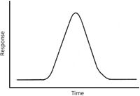
Let's start with a leading and hopefully thought-provoking question: If a pure sample is eluted from a gas chromatography (GC) column operated in its normal fashion, and there is no detector, what is the peak shape at the end of the column? The dynamic processes of GC are well understood, and we can model the processes of molecular diffusion in the mobile and stationary phases to arrive at an answer. If the sample is a pure compound and the diffusion processes are unperturbed, then the sample will be eluted within a symmetrical peak shape as shown in Figure 1, with the x-axis representing time after sample injection at the front of the column and the y-axis representing some parameter proportional to the amount of sample eluted from the column. The time point at which the mass flow rate from the column reaches a maximum is called the retention time, and this is labeled on the figure. On the same column, using the same GC conditions, the retention time should be reproducible, and it can be used as a factor in identifying the sample. One analytical principle to keep in mind here is that of "necessary and sufficient." More precisely, if the retention time of a reference standard is known, then if the unknown sample is the same compound as the reference it will be eluted at the same retention time. However, if the unknown sample is eluted at the same retention time, it may be the same compound as the reference. To be sure of our identification we need more information, and that brings us to information provided by the detector other than just a determination of the retention time. We want a detector that provides additional and characteristic information, which brings us directly to MS. Although chromatography coupled with mass spectrometry seems like the marriage made in heaven, we should always be aware of the mutual give-and-take in the relationship. In this column, we discuss the dynamic characters of our techniques, and we will start very simply.

Figure 1: This symmetrical shape is the idealized representation of a peak eluted from a GC column. The x-axis is time after injection of the sample onto the column, and the y-axis is a detector response proportional to the amount of sample eluted from the column.
Detector Characteristics
The characteristics of the detector determine the nature of the y-axis parameter in Figure 1. If the detector operates to produce a response that is directly and linearly proportional to the mass flow of the sample entering it, and if it operates to produce a measureable signal in a time frame much shorter than incremental changes in mass flow, then the measured peak shape with this detector is very close to the modeled peak shape. If the detector produces a response that is concentration-dependent, then the relevant proportionality factor will change the appearance of the peak, although the peak shape may still be symmetric overall. If the detector operates in such a fashion that it provides a signal from some types of eluted sample molecules and not others (such as with an electron-capture detector), then the proportionality factor for the y-axis response changes from sample to sample and peak to peak. Most modern GC detectors produce a near-instantaneous response, so that the x-axis in Figure 1 remains directly proportional to time. We can foresee that if the detector itself has dynamic characteristics that have a scale that is similar to the dynamics of the elution of the GC peak, then a proportional factor must be applied to the x-axis as well.
The quintessential GC detector that provides the wealth of information needed to identify compounds as they are eluted from the column is the mass spectrometer. Accordingly, we need to evaluate the role of MS as a GC detection method in terms of its response characteristics that may provide a proportionality factor that changes the y-axis (response) or the x-axis (time) in Figure 1. Many types of ionization methods, mass analyzers, and detectors used in MS have been previously described in this column. The definitive matrix for MS ionization methods and their mass- or concentration-dependent response factors across all types of compounds is a construct that will probably never be completed. It cannot be predicted with specificity, and therefore the calibration curve for the particular sample of interest remains a reliable method to establish the proportionality on the y-axis. In the remainder of this column, we discuss the dynamic nature of mass analysis using various types of instruments and describe the effects of that analysis on the measured elution profile of a GC peak (the x-axis).
Dynamic Mass Analysis
The time required for mass analysis, specifically the scanning of the mass analyzer, is usually the parameter of concern in assessing whether a representational GC peak elution profile can be measured. This was more of a concern in the past than it is now. However, contemporary technical notes available on the web sites of multiple instrument vendors describe the effect of scan rate on the measured GC peak profile and tout the fast scan rate of their instruments. Figure 1 represents the idealized result of a detector that instantaneously produces a signal. But every mass spectrometer needs at least some time to differentiate between ion masses and measure ion flux. Leaving aside dispersive instruments, in which ions within a specified mass range are considered to be simultaneously detected, instruments with a single-channel detector will use some means to differentiate ions by mass that involves a dynamic time parameter. Perhaps the simplest mass analyzer is the time-of-flight (TOF) instrument, in which the time required for ions of different masses to traverse the instrument from the source to the detector is measured and then converted to the ion mass through a simple mathematical relationship.
It is interesting to recall that some of the first commercial TOF instruments were marketed as detectors for GC. At that time, the GC column technology provided relatively broad peak elution profiles. Then, as now, the ionization method had to be operated in a pulsed rather than a continuous fashion, and the TOF mass analysis was completed within a few microseconds for each individual "scan." This speed of spectral data acquisition could resolve even slightly overlapped peaks in the GC elution profile. The ultimate rate-determining step in these earlier TOF instruments was the speed at which the data could be collected and collated. But the speed at which this step could be accomplished was still rapid compared to the width of the GC peak. In modern GC, the peaks are far narrower, but concomitantly, the electronics of TOF instruments are also much faster. Thus, the dynamic character of the TOF mass analysis (microseconds) is still usually orders of magnitude shorter than the elution profile (seconds).
Common scanning mass analyzers are magnetic sector instruments and quadrupole-based mass filters. In their GC–MS configurations, these analyzers are coupled to a continuous ionization source such as an electron ionization or chemical ionization source. Sample compounds are eluted from the column into the source, where a continuous flux of ions is created and transported into the mass analyzer. Scanning a magnetic sector mass analyzer is a complex process. The electromagnet may exhibit hysteresis and may require a settling time, and temperature control of a large mass of the magnet may also become important. The relationship between the mass of the ion passing through the instrument from the source through the analyzer to the detector is given by m/z = (B2 r2 /2V) where m/z is the mass-to-charge ratio, B is the magnetic field strength, r is the radius of the electromagnetic sector, and V is the accelerating voltage. The linear scan of B is therefore not linear with mass, and for technical reasons, often proceeds from a higher mass to a lower mass. The data processing system automatically converts the signal from the detector from a nonlinear scan into the linear scale of m/z. Any assumption that each m/z window in the spectrum is monitored for the same period of time is therefore not valid. For instance, a total scan time of 70 ms (quoted in recent vendor literature for a magnetic analyzer GC–MS instrument) must be apportioned across the selected mass range factoring in the actual scan of B, the magnetic field strength. The instrument operator should not hesitate to dive into the details of what is going on and to understand the dynamic nature of instrument operation.
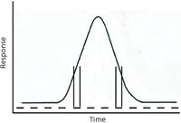
Quadrupole mass filters were combined into commercial GC–MS instruments in the 1970s, and marketed as smaller, faster-scanning mass analyzers (1). Because scanning is accomplished electronically, the scan function can be linear, bidirectional, or even nonsequential in mass. The speed is limited by the stability of the driving electronics, the response time of the detector, and the speed of the data acquisition process. This simple scan function provides the opportunity to use this instrument as a platform to delineate the interaction of scan time for the mass analyzer with elution time of a peak from the GC system. Figure 2 overlays the scan function on the elution profile of a peak; only alternate scans are shown for clarity. The vertical lines shown for two scans intercept the peak profile and show that the amount of sample in the source is changing during the time required to scan the mass analyzer. In this example, the time required for the scan is purposefully chosen so that it is similar in scale to the time required for the elution of the peak. On the leading side of the peak, the flux of the sample ions increases during the time required for a scan of the mass analyzer. On the trailing side of the peak, the flux decreases during the scan time. If the y-axis is assumed to be proportional to sample flux, then the change in flux over the course of any given scan can easily cover a 2–3-fold range. This far exceeds the expected error in accuracy in measuring ion intensities (which is ±10% in the most generous of situations). So, what is the expected change in the measured mass spectrum caused by this change in sample flux? Assume that the scan direction is from low-mass to high-mass. Mass spectra recorded on the leading edge of the peak will have peak intensities at higher masses that are elevated over reference spectra levels. Conversely, assuming the same scan direction, mass spectra recorded on the trailing edge will have peak intensities at higher masses that are depressed below reference spectra levels.

Figure 2: Ideal signal for a peak shape with discrete scans of the detector shown across the width of the peak. Only every other scan is indicated in the scan line, for clarity. The mass flow varies significantly over the course of each scan of the analyzer, as shown by the intercept of the vertical lines on the peak profile.
Choosing your Mass Spectra
So which of these mass spectra do we choose to search against the library to identify the compound that just was eluted from the GC column? If we choose mass spectra recorded on the leading or trailing edge of the peak, there will be a scanning bias in the recorded mass spectrum that could throw off the validity of the library search. Do we then hope to catch a mass spectrum recorded right at the top of the peak, when the relative change in the flux of the sample entering the mass spectrometer might be minimized? We do not. Instead, our normal practice is to add together and average all of the scans recorded across the width of the peak, so that any scanning bias on one side is counterbalanced by the reverse bias on the other edge. Given a symmetrical peak shape, the assumption is justified, and the data processing software performs this function automatically and in the background. A general rule of thumb is that 8–12 scans recorded across the width of the peak will provide an accurate representation of the peak after processing and an accurate peak area that can be used for quantitation. Fewer scans may still provide a mass spectrum sufficient for identification purposes, but the connect-the-dots peak profile generates errors in the peak area values.
Other Considerations
To reach our desired number of scans across GC peaks that have become narrower, we require ever-faster scan speeds. The achieved scan speed is a combination of how fast the analyzer can scan, how fast the detector signal can be digitized, how fast the data can be stored, and how wide the desired mass range is. But there is yet another assumption, and that is that the ions (of whatever mass) are moving at a velocity sufficient to transit the analyzer in the short mass window imposed by the scan rate. For example, an ion entering the front of a quadrupole mass filter has to make it all the way through to the detector before the analyzer conditions switch to the "next" mass. Furthermore, the ion's flight through the filter is not a linear one. Instead, ions in stable trajectories follow oscillating paths. More details are beyond the scope of this column, other than to note that ion transit times become a concern at the very fastest scan rates. How fast is this rate? One vendor describes the top scan speed as 12,500 Da/s across a mass range of 150 Da. The time listed as required for a full scan is 0.01 s, and the interscan settling time is 0.0006 s. At the quoted scan speed of 625 Da/s, a full scan requires 0.2 s, and the settling time is 0.01 s. There are several intermediate settings, of course. The scan rate chosen by the analyst will depend on the expected narrowness of the GC peaks. If most GC peaks are a few seconds wide, with the narrowest perhaps 1-s wide, then the slower scan speed will only provide about five scans across that narrowest peak, and that will probably not be enough for quantitative purposes. However, that set of conditions may suffice for the other GC peaks. If the desired mass range is 450 Da (say from m/z 50 to m/z 500), then the quoted times for a full scan at a given scan speed will be three times longer. In that case, the system may record only one or two scans across a 1-s wide peak, and the changes in flux of the sample during the elution profile will probably distort the mass spectrum excessively across many GC peaks. The prepared analyst selects a scan speed option fast enough to cover the expected chromatographic conditions. In analysis of unknowns, that may be a "guess" based on experience.
Concluding Remarks
This column closes with a brief discussion of two other situations in which the dynamic nature of chromatography interacts with the dynamic nature of the scanning mass spectrometer. The first of these is the selected ion monitoring (SIM) experiment. In SIM, the mass range is not scanned continuously from one end of the range to the other. Instead, the mass analyzer is set to sequentially pass selected ions of different masses. The mass analyzer reaches the first mass conditions, resides there for a specified time window, and then switches to the next selected mass. The effective scanning speed is therefore related to how quickly the analyzer can move from one mass window to the next, and by extension, to how quickly the analyzer can step through the sequence. A SIM experiment can monitor changes in the elution profile intensities for one ion, 10, or 20. The time variation in signals for each of the mass-selected ions should reflect the elution profile of the peak. It is also possible for the data system to transition from recording full-scan mass spectra to a SIM mode in real time, providing full mass spectra for library searching and SIM data for lower limits of detection. The ability to switch between the two data acquisition modes for narrow peak widths emphasizes the need for a high scan speed and a stable scan function of the mass analyzer.
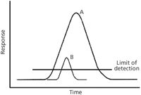
I chose the second situation to highlight the importance of understanding dynamics as it begins in Figure 1, in which we assume that the profile represents the elution of a single pure compound A from the chromatograph. Now, moving to Figure 3, we add the elution profile for a smaller amount of a nearly coeluted peak B, and ask whether MS information can provide evidence for this second component and how scan rates matter in our assessment. A horizontal line for the limit of detection is also provided in Figure 3. A scan rate sufficient to characterize the peak A profile must be several times faster to characterize the profile of peak B for two reasons. The limit of detection effectively narrows the peak B elution profile. Furthermore, the peak B elution profile is a subset of the peak A elution profile that must be differentiated. A first approximation is that two nearly overlapped peaks narrow the effective elution profile by a factor of 2. Three nearly coeluted peaks narrow the effective profile for a single peak by a factor of three. The demand for faster scan speed increases concomitantly. Faster scan speeds that seem to provide an over-determination of peak profiles via processing of full mass spectra provide a large set of data that can be mined for any evidence of coeluted samples near the limit of detection.

Figure 3: A smaller amount of a nearly coeluted peak may provide a detector response very near the limit of detection, and as a consequence, a narrower effective peak width.
Reference
(1) C. Brunee, Int. J. Mass Spectrom. Ion Proc.76, 125–237 (1987).
Kenneth L. Busch enjoys the strange looks that he gets while explaining the cut-and-weigh method of determining peak areas in strip-chart record gas chromatography to the younger analytical chemists. However, he is forced to admit that sharp scissors were taken away from him in fourth grade, and he settled for folded colored construction paper until sophomore year in college, when integrating circuitry captured his attention. Back in the early years, GC peaks were still tens of seconds wide, GC columns were packed by hand, and mass spectrometers scanned at glacial speeds. Younger folk tell the story that things are different now, reaching levels characterized as instant gratification. This column is the sole responsibility of the author, who can be reached at wyvernassoc@yahoo.com.

Kenneth L. Busch

LIBS Illuminates the Hidden Health Risks of Indoor Welding and Soldering
April 23rd 2025A new dual-spectroscopy approach reveals real-time pollution threats in indoor workspaces. Chinese researchers have pioneered the use of laser-induced breakdown spectroscopy (LIBS) and aerosol mass spectrometry to uncover and monitor harmful heavy metal and dust emissions from soldering and welding in real-time. These complementary tools offer a fast, accurate means to evaluate air quality threats in industrial and indoor environments—where people spend most of their time.
NIR Spectroscopy Explored as Sustainable Approach to Detecting Bovine Mastitis
April 23rd 2025A new study published in Applied Food Research demonstrates that near-infrared spectroscopy (NIRS) can effectively detect subclinical bovine mastitis in milk, offering a fast, non-invasive method to guide targeted antibiotic treatment and support sustainable dairy practices.