The Importance of Method Development for Trace-Element Analysis by Inductively Coupled Plasma–Optical Emission Spectroscopy
Selecting the correct wavelengths or isotopes and optimizing flame, furnace, or plasma conditions can seem a daunting task for a novice user, with a multitude of opportunities to introduce errors and generate poor quality data. While most elemental analysis instruments have intuitive operating software, they lack the intelligence to guide the operator through the early stages of method development and overcome associated problems along the way. This study describes an automated, intelligent approach to method development for trace element analysis using optical emission spectroscopy, and exemplifies this capability with a suite of real-world sample matrices.
Selecting the correct wavelengths or isotopes and optimizing flame, furnace, or plasma conditions can seem like a daunting task for a novice user, with a multitude of opportunities to introduce errors and generate poor quality data. While most elemental analysis instruments have intuitive operating software, they lack the intelligence to guide operators through the early stages of method development and overcome associated problems along the way. This study describes an automated, intelligent approach to method development for trace-element analysis using optical emission spectroscopy, and exemplifies this capability with a suite of real-world sample matrices.
Since its introduction more than 40 years ago, inductively coupled plasma–optical emission spectroscopy (ICP-OES) has significantly changed the capabilities of elemental analysis. This technique combined the energy of an argon-based plasma with an optical spectrometer and detection system capable of measuring low-level emission signals, which allowed laboratories to perform rapid, automated, multielement analyses at trace concentrations (1). This introduction occurred approximately 10 years before the introduction of the first commercial inductively coupled plasma–mass spectrometry (ICP-MS) system, so ICP-OES systems became the workhorse instruments in many laboratories required to perform elemental analysis at trace-level concentrations. The sensitivity, speed of analysis, ease of use, and tolerance to high levels of dissolved solids makes ICP-OES a technique that laboratories continue to rely on, decades after its inception (2,3).
As with many techniques, its success in the laboratory depends upon the quality of the methods that are developed for the application work being conducted. While ICP-OES instruments provide automated, intuitive operation with parts-per-billion detection limits and working ranges that extend over several orders of magnitude, developing a useful, well optimized analytical method can be a labor-intensive and time-consuming process.
The quality of any developed and optimized analytical method can be assessed by a number of different figures of merit, including accuracy, precision, sensitivity, speed, working range, ease-of-use, and reproducibility. Both the instrument operating conditions and method parameters can affect these performance characteristics, so it is important to be familiar with these factors and understand their effects on the analytical data being collected.
It is not the intention of this column installment to denigrate the importance of developing an optimum sample preparation method for a given sample type. If sample preparation is not approached with careful and thoughtful consideration, the instrument method will not compensate for it. There are many potential pitfalls when preparing samples for analysis, including contamination, loss of volatile elements, incomplete dissolution, creation of an unstable solution, and alteration of the elemental species present in the original sample. Any of these issues will produce poor quality data, regardless of the robustness of the instrument method. However, for the purposes of this article, it will be assumed that optimized sample preparation procedures have been developed.
Method Development Considerations
Whether a method is being developed from scratch or an existing method is being further optimized, there are a number of parameters that should be taken into consideration to ensure the method is best suited for the intended application. These include
- Analytical wavelengths
- Interferences
- Plasma parameters
- Data acquisition parameters
- Validation of method
Let’s take a look at each of these considerations, in turn, to understand how each factor plays a role in the quality of the final optimized method. It should be noted that the theory behind this approach is applicable to the development of an analytical method for any elemental analysis technique; however, some of the specific considerations will change. For example, if developing an analytical method for an ICP-MS application, one would be choosing isotopes instead of emission wavelengths for measuring the analytes and internal standards.
Analytical Wavelengths
When choosing appropriate wavelengths for the elements of interest, it’s important to keep in mind the method’s desired performance attributes. For example, if method development is taking place for quantifying trace elements in drinking water samples, the main performance attributes will likely be detection capability and accuracy. Therefore, the most sensitive wavelength should be chosen for each element and all potential interferences should be identified and carefully corrected. Alternatively, if a method is being developed to quantify elements in oil additives a wider working range may be desired. In this case, wavelengths with lower sensitivity may need to be chosen to maximize the concentration range over which the elements can be calibrated.
A critical factor in determining the suitability of a wavelength is whether it suffers from interferences. Several types of interferences exist in ICP-OES, and their severity is dependent on the analyte wavelength, other elements present in the sample, and the sample matrix itself (4). Evaluating interferences is not a trivial task and must be carried out with a great deal of care and thought. Interferences that are erroneously identified or not compensated for correctly will result in poor quality data. With the number of interference types and the variety of correction approaches possible, interference correction can quickly become an overwhelming task, particularly to an inexperienced operator. For this reason, when addressing interferences the following wavelength selection procedure is recommended:
1. Choose several wavelengths for each element in the method
2. Collect analyte wavelength scans
3. Visually inspect the peaks for the data collected
4. Review data
5. Eliminate unsuitable wavelengths
Let’s review this process in more detail. In the first step, it is recommended to choose two or three wavelengths for each element of interest. This includes both the analyte elements and any applicable internal standard elements. Typically, the most sensitive wavelength for each element would be chosen, along with two wavelengths of slightly lower sensitivity. If a wide range of concentrations is expected to be encountered in the samples, a high sensitivity wavelength might be chosen along with a low sensitivity wavelength. In some cases, the sample matrix will produce an emission spectrum that is so complex, there may be only one or two suitable wavelengths (interference free and providing the desired working concentration range) to choose for the analysis.
After a set of wavelengths has been chosen for evaluation, data should be collected to determine which wavelengths are best suited, based on the requirements of the application. It is recommended that three wavelength measurements be collected for each of the following solutions:
- A blank (calibration and method blanks, where applicable)
- A low-concentration calibration standard
- A high-concentration calibration standard
- A sample that represents each type of sample matrix to be analyzed
Data from the blank provides an emission profile of the matrix in the absence of analytes. Data from the calibration standards provides profiles for the elements of interest at low and high concentrations. Both sets of measurements are required for the data inspection outlined in steps 3 and 4 described earlier. The highest concentration calibration standard should be used for this data collection to ensure that none of the selected wavelengths suffer from peak broadening or self-absorption (5). Sample measurements produce emission profiles for the elements of interest in the presence of the sample matrix. One sample for each matrix type should be collected to ensure emission profiles are examined in every applicable sample matrix. For laboratories analyzing a wide range of sample matrices, collecting wavelength measurement scans for each matrix type could require data collection for a large number of samples.
After wavelength data has been collected, they should be visually inspected to determine that the emission peaks have the proper shape and size. An ideal wavelength would produce the series of emission signals illustrated in Figure 1. In Figure 1, the emission from the blank produces a flat emission signal with a relatively low intensity. The emission signals for the calibration standards and representative samples should produce a symmetric, Gaussian-like shape with a single peak. Each peak should exhibit a proportional change in magnitude to match the difference in concentrations. For example, data from a standard containing elements at 1.0 ppm would be expected to have approximately twice the signal of that for a 0.5 ppm standard, while maintaining approximately the same shape.
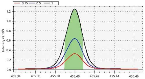
Figure 1: Examples of emission profiles for three calibration standards and a blank.
Numerical data should be inspected to determine the intensity and precision at each wavelength. The intensity for each standard should increase at a rate that is proportional to the increase in its concentration. If a set of three wavelength measurements was collected for each solution, the measured intensities can be used to calculate the approximate precision for each measured standard. Calculated precision values should be within the acceptable limits for the application.
Interferences
Interferences are common with any plasma-based technique, particularly when trying to measure trace-level concentrations in a sample matrix that contains high concentrations of elements that produce line-rich spectra, such as Fe, Ca, and Si (6). Sample matrices that are known to generate these types of interferences include geological, metallurgical, and high-matrix environmental samples, such as soils or wastewaters. The three common types of interferences in ICP-OES are physical, chemical and spectral.
Physical Interferences
Physical interferences occur when the nebulization or transport efficiency of the standards differs from that of the samples. These differences in the physical characteristics of the matrices (density, viscosity, level of dissolved solids) can produce errors in the measured sample concentrations. Physical interferences are typically not wavelength specific and can be overcome by using internal standards and preparing the calibration standards in a matrix that matches that of the samples (7).
Chemical Interferences
Chemical interferences occur when the standards behave differently from the samples as they enter the plasma. These types of interferences typically result from changes in temperature within the plasma and include easily ionized element (EIE) effects, molecular emission, and plasma loading. Referring to Figure 2 (4), the plasma consists of several temperature zones, which translate to varying amounts of energy available for excitation of the ground-state atoms. The plasma is hottest and contains the greatest amount of energy at its base, which is where the sample is introduced. In this region, the plasma contains sufficient energy to atomize and ionize elements before they are excited. Ionization is particularly prevalent for elements in the first two groups of the periodic table, which all have relatively low first ionization potentials. These easily ionized elements include elements such as Na, K, and Li.
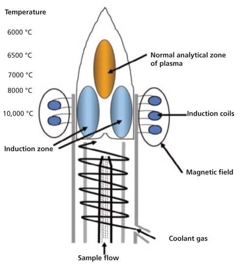
Figure 2: Different temperature zones within a plasma discharge.
When easily ionized elements are present at low concentrations, very few of the atoms become ionized, which means emission will take place from excited atoms. At high concentrations, a significant number of the atoms will become ionized, which shifts the emission wavelength such that it will predominantly occur from the excited ions. If left uncorrected, this interference will reduce the linear dynamic range of the calibration curve and can potentially produce highly inaccurate results (8).
This type of interference can be corrected by adding an ionization suppressant (also known as an ionization buffer) to all the solutions before analysis. An ionization suppressant is a solution containing a high concentration of an easily ionized element (1000 ppm Cs, for example). The solution will produce an extremely high concentration of cesium ions in the plasma, which, according to Le Châtelier’s principle (9), will reduce the concentration of ions and increase the concentration of atoms to provide a chemical equilibrium balance in the plasma. Therefore, the element of interest will remain in its atomic state in the plasma.
If a dual-view instrument is being used, an additional step to take in correcting for this type of interference is to also measure the emission radially. EIE effects are much more significant for axial plasmas as emission is being measured from species that are present in all temperature zones within the central channel of the plasma. If emission is measured perpendicular to the direction of the plasma (radial view), emission will be measured from a single temperature zone (10).
Converse to the formation of EIE interferences are the formation of molecular interferences. If we refer again to Figure 2, the tip (also known as the tail) of the plasma is the coolest and least energetic part of the plasma (11). In this region, atoms and ions that were formed in the hotter part of the plasma can combine to form molecules. These molecules can become excited and emit light, which will produce broadband, molecular emission spectra.
This type of interference is relatively straightforward to correct and requires very little intervention from the analyst. Since the coolest part of the plasma is in its tail, removing that portion of the plasma prevents atoms and ions from traveling through a zone that’s cool enough to allow them to combine and form molecular species. All modern ICP-OES instruments are set up to automatically and effectively remove the tail of the plasma. There are a variety of methods in which this is accomplished-a flow of inert gas that is counter to the direction of the plasma, a high velocity shear gas, or a cooled cone interface; however, all are effective in cutting off the tail of the plasma. An example of how the plasma tail is removed is illustrated in Figure 3.
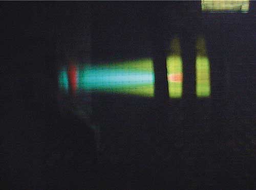
Figure 3: An example of how the plasma tail is removed.
As with chemical interferences, another option for eliminating molecular interferences is to measure emission from a radially configured plasma. If emission is collected at 90° to the plasma and the observation height is optimized, emission should be collected from the “normal analytical zone,” which is well-separated from the cooler tail of the plasma.
Plasma loading is an interference that is sometimes experienced when samples contain organic solvents or high levels of dissolved solids (12). When a significant amount of material is introduced into the plasma, it cools the plasma and, in severe cases, can extinguish it completely. Cooling the plasma reduces the amount of available energy, which affects the emission intensity of the elements present. As a result, if samples contain concentrations of dissolved solids that are different from those in the standards, the emission intensity for the same analyte concentration will be different in the samples and standards which could produce data inaccuracies. This interference can usually be addressed by preparing standards in a matrix that matches that of the samples, using correct internal standards, choosing sample introduction components that were designed for the application, and selecting sample introduction conditions that minimize plasma loading.
Spectral Interferences
The third and sometimes most challenging type of interferences are spectral. These interferences occur when emission from one or more species in the sample matrix overlaps with the emission for the analyte of interest. These interferences can result in a background shift, a partial peak overlap, or a direct overlap. If the analyte is suffering from a direct spectral overlap, the interfering element must either be removed from all solutions before analysis, or an alternative wavelength must be selected. If the interfering element produces a simple background shift (either a flat, raised baseline or a sloping background), the analyte can be accurately quantified by the use of optimized background correction points.
If the analyte suffers from partial spectral overlap, a combination of background correction and mathematical correction may need to be used. An example of partial spectral overlap is illustrated in Figure 4, which depicts data for a solution containing 1 ppm B in a matrix containing 100 ppm Fe.
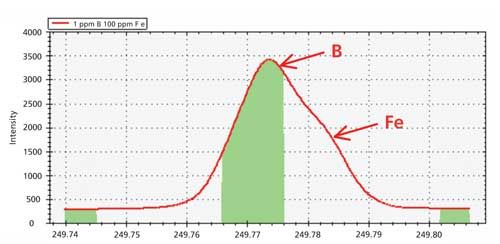
Figure 4: Emission profile of 1 ppm B in a matrix containing 100 ppm Fe.
A shoulder is clearly visible on the right side of the main peak, indicating the presence of a spectral overlap on B at 249.773 nm. If the emission profile for the sample solution is overlaid with that of single-element solutions containing 1 ppm B and 100 ppm Fe, the image in Figure 5 is produced.
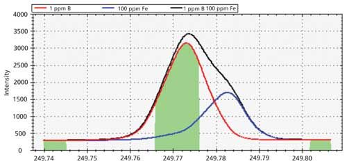
Figure 5: Emission profiles to demonstrate spectral overlap.
In this figure, the red peak represents the emission profile for 1 ppm B at 249.773 nm, whereas the blue trace represents the emission peak for 100 ppm Fe at 249.782 nm. The black outline represents the combined emission from a sample containing 1 ppm B and 100 ppm Fe. The center green-shaded region represents the area under the peak that will be used for data collection. This area includes a portion of the emission peak from Fe and, if left uncorrected, this analytical measurement might produce erroneous data.
The best way to correct for this interference is to select an alternative emission wavelength for B that is free from interferences. If an alternative wavelength cannot be used, an interelement correction (IEC) factor should be calculated to correct for the overlap of Fe on B. If IEC factors are used, they must be carefully calculated and applied to ensure spectral overlaps are being accurately corrected. Improperly calculated IEC factors can produce data that are more erroneous than if no IEC factors were used (13).
Plasma Parameters
Optimum plasma operating conditions are as critical as correct wavelength selection and interference correction procedures. Plasma parameters will impact the stability and energy of the plasma and, therefore, the behavior of the elements, and are typically optimized to maximize the emission intensity for the analyte wavelengths in the method.
Plasma parameters to consider for optimization are
- RF power
- Nebulizer gas flow
- Auxiliary gas flow
- Coolant gas flow
- Radial viewing height
It should be noted that, while important, plasma optimization is usually not as critical as the other method development steps. ICP-OES methods typically are developed for the analysis of multiple elements. Each element prefers a slightly different set of plasma parameters to achieve its maximum intensity for the wavelength selected. Because ICP-OES instruments collect emission intensities from groups of elements simultaneously, it is not practical to select different plasma settings for each individual element. Therefore, the plasma settings for multielement analysis will be somewhat of a compromise for most of the elements in the method. Most modern ICP-OES instrumentation provides an automated optimization feature to rapidly and automatically select the best plasma parameters to maximize the emission intensity for as many elements as is possible in a multielement method (14).
Data Acquisition Parameters
The data acquisition parameters are another set of method development conditions to consider for optimization. They include the choice of axial or radial plasma viewing (if using a dual view instrument), the integration time, and the number of integrations. In general, an axial plasma is used for determining low, parts-per-billion concentrations, while a radial plasma view is used for higher (parts-per-million) concentrations or to help compensate for chemical interferences (15). The integration time for each plasma viewing configuration must be long enough to collect sufficient emission from all elements being measured. This time would usually be dictated by the element with the weakest emission line or the element that is present at the lowest concentration. An axial integration time of 15 s and a radial integration time of 5 s are fairly typical to use. Finally, the number of integrations or measurements must be set. Keep in mind that if every sample is collected using a single integration, statistical analysis and precision data and limits of quantitation cannot be calculated and reported. Therefore, two or more integrations must be collected for each sample to report this kind of information.
Validation
The final step in the method development process is to validate that the method will produce results that meet the figures of merit required for the application. Methodology that achieves good detection limits, yet cannot obtain the required accuracy is unlikely to meet the data quality objectives of the analysis. A detection limit study is always encouraged for any analytical method. Calculated detection limits and limits of quantitation allow reporting limits to be calculated to determine the lowest concentrations that can be measured and reported for a suite of elements in a given sample matrix (16).
Regardless of whether a detection limit study is performed, the developed method needs to be validated before use with real samples. The best approach to validating an analytical method is to obtain a certified reference material (CRM) that is appropriate for the application. If an analytical method is valid for the application, data acquired for a suitable CRM should match the certified concentrations that accompany the CRM (within defined error limits).
If a suitable CRM is not available for a given application, a number of other check standards can be used. A calibration standard can be prepared and analyzed as a sample to see if the concentration is at the level it should be. A calibration or quality control (QC) standard can be purchased from an external source and analyzed as a sample. Samples can be prepared and measured in duplicate to determine the precision of the method. Samples can be spiked with a known concentration of the elements of interest to determine whether the spiked elements can be measured and recovered at their expected concentrations. If interference corrections are being used, interference check standards can also be prepared or purchased and analyzed to ensure that the correct results are obtained.
Summary
Correct and optimized method development cannot be overemphasized when performing trace-element measurements by ICP-OES, or any other elemental analysis technique. Even though it can be a labor-intensive process, a poorly developed method has the potential to produce erroneous data. Conversely, a thoughtful method development strategy could be useful for several different applications with minimal modifications. This article has provided an overview of some of the main factors that should be taken into consideration when developing an optimized ICP-OES method.
References
- K. Ohls and B. Bogdain, J. Anal. At. Spectrom. 31, 22–31 (2016).
- C. Veillon and M. Margoshes, Spectrochim. Acta, Part B23(8), 503–512 (1968).
- R.H. Wendt and V.A. Fassel, Anal. Chem.37(7), 920–922 (1965).
- G.F. Larson, V.A. Fassel, R.H. Scott, and R.N. Kniseley, Anal. Chem. 47(2), 238–243 (1975).
- H.G.C. Human and R.H. Scott, Spectrochim. Acta, Part B31(8–9), 459–473 (1976).
- “Overcoming Interferences with the Thermo Scientific iCAP 7000 Plus Series ICP-OES,” Thermo Fisher Scientific Technical Note, available at: http://www.thermoscientific.com/content/dam/tfs/ATG/CMD/cmd-documents/sci-res/app/ea/icp-oes/TN-43332-ICP-OES-Overcoming-Interferences-iCAP-7000-Plus-Series-TN43332-EN.pdf.
- R.F. Browner in Inductively Coupled Plasma Emission Spectrometry, Part II, Applications and Fundamentals, P.W.J.M. Boumans, Ed. (Wiley-Interscience, New York, 1987), pp. 244–288.
- M.W. Blades and G. Horlick, Spectrochim. Acta, Part B36(9), 881–900 (1981).
- A.J. Miller, J. Chem. Educ.31(9), 455 (1954).
- M.H. Abdallah, R. Diemiaszonek, J. Jarosz, J.M. Mermet, J. Robin, and C. Trassy, Anal. Chim. Acta84, 271–282 (1976).
- I.B. Brenner and A.T. Zander, Spectrochim. Acta, Part B55(8), 1195–1240 (2000).
- A.W. Boorn and R.F. Browner, Anal. Chem.54, 1402–1410 (1982).
- V. Thomsen, D. Mercuro, and D. Schatzlein, Spectroscopy21(7), 32–40 (2006).
- P.W.J.M. Boumans, Inductively Coupled Plasma Emission Spectrometry, Part I, Methodology, Instrumentation and Performance (Wiley-Interscience, New York, 1987), pp. 100–255.
- F.V. Silva, L.C. Trevizan, C.S. Silva, A.R.A. Nogueira, and J.A. Nóbrega, Spectrochim. Acta, Part B57, 1905–1913 (2002).
- T.R. Dulski in A Manual for the Chemical Analysis of Metals (ASTM, 1996), pp. 200–201.

Maura Rury is the Regional Marketing Manager for the Trace Element Analysis Group in the Chromatography and Mass Spectrometry Division at Thermo Fisher Scientific in Waltham, Massachusetts. Direct correspondence to: maura.rury@thermofisher.com

Atomic Perspectives: Highlights from Recent Columns
March 3rd 2025“Atomic Perspectives,” provides tutorials and updates on new analytical atomic spectroscopy techniques in a broad range of applications, including environmental analysis, food and beverage analysis, and space exploration, to name a few. Here, we present a compilation of some of the most popular columns.
Pittcon 2025: Highlighting Talks on Atomic Spectroscopy
February 26th 2025At Pittcon this year, there will be numerous sessions dedicated to spotlighting the latest research that uses atomic spectroscopy or elemental analysis techniques. We highlight some of these talks below that might pique the interest of spectroscopists and researchers attending the conference this year.