Raman Spectroscopy and Imaging of Low Energy Phonons
Raman bands in the low energy region of the spectrum of crystals are attributed to so-called external lattice vibrational modes. The Raman bands from these external vibrational modes (low energy phonons) are very sensitive to crystal structure and orientation with respect to the incident laser polarization and to molecular interactions within the crystal. The low energy vibrational modes of many organic molecular crystals have very high Raman scattering cross-sections. Raman spectra and images of low energy phonons in so-called two dimensional (2D) crystals such as few-layer MoS2 reveal spatial variations in the solid state structure that are not evident in the higher energy bands.
Raman bands in the low-energy region of the spectrum of crystals are attributed to so-called external lattice vibrational modes. The Raman bands from these external vibrational modes (low-energy phonons) are very sensitive to crystal structure and orientation with respect to the incident laser polarization and to molecular interactions within the crystal. The low-energy vibrational modes of many organic molecular crystals have very high Raman scattering cross-sections. Raman spectra and images of low-energy phonons in two-dimensional (2D) crystals such as few-layer MoS2 reveal spatial variations in the solid-state structure that are not evident in the higher-energy bands.
In chemistry courses we learn about Raman scattering through the interaction of light with molecules. A molecule, initially in the ground state, interacts with an incident photon driving the molecule to a virtual energy state whereupon it drops to the first excited vibrational state and emits a photon (Stokes Raman scattering). The energy difference between the incident and scattered photons is equal to the energy difference between the ground and first excited vibrational states. If the molecule initially had been in the first excited vibrational state and ended in the ground state, a quantum of energy would have been transferred from the molecule to the scattered photon and its energy would have been greater than that of the incident photon (anti-Stokes Raman scattering). Hence, one can observe the Raman spectrum at either longer (Stokes) or shorter (anti-Stokes) wavelengths relative to that of the incident monochromatic laser beam.
When dealing with gases or liquids it is appropriate to speak of the interaction of a photon with individual molecules. However, very often we deal with solid-state materials for which there may be no molecular species-for example, TiO2, Si, C (graphene or diamond), and CaCO3. Raman spectroscopy of solid-state materials involves the inelastic scattering of light by phonons, quanta that have the energy of lattice vibrations. The Stokes and anti-Stokes Raman scattering consist of the generation or annihilation of a phonon in the solid, respectively. In crystalline materials, the phonons can be understood as lattice vibrational modes whether the crystal is a covalent or ionic solid or a molecular crystal such as TiO2, BaF2, or H2O (ice), respectively.
When speaking of Raman spectra of solid-state materials, some spectroscopists will describe certain bands as phonons and others as molecular vibrations. Strictly speaking, this is not correct; all of the bands in a Raman spectrum of a solid arise from phonons. A more appropriate distinction is to speak of external and internal lattice vibrational modes when speaking of solid-state Raman band assignments, particularly for molecular crystals (1). An external vibration can be thought of as the collective motion of molecules as a whole, such as whole water molecules moving collectively in an ice crystal. Some low-energy Raman bands are a result of shear or interlayer breathing modes of the crystal layers. The shear modes can be pictured as atomic or molecular layers moving antiparallel to each other within their planes whereas the breathing modes involve the layers moving away from and toward each other. The external vibrations are generally of low energy and of course would be absent from the liquid or gas spectrum of the material because of the absence of long-range translational symmetry present in a crystal. The internal vibrational modes arise from the coupling through the crystal of the local vibrational modes observed for the molecular species. We can think of these types of phonons as collective local modes modified through coupling with other molecules in the crystal and affected by their arrangement in the lattice. Their Raman shifts are often similar but not identical to those of the molecular (liquid or gas) spectrum.
As you may expect, the external vibrational modes or low-energy phonons are very sensitive to crystal structure. That is why the external modes have proven so useful in the pharmaceutical industry for the characterization and screening of polymorphs. In addition, Raman spectra of low-energy phonons are dependent upon the crystal orientation with respect to the incident laser polarization. Perhaps less well known is the sensitivity of the external modes to molecular interactions such as hydrogen bonding or even the weaker van der Waals forces between molecular or atomic layers. Here, we discuss those aspects of chemical bonding and structure that affect the Raman spectroscopy of low-energy phonons and demonstrate the practicality of imaging them for the characterization of 2D crystals.
Stokes, Anti-Stokes, and Temperature
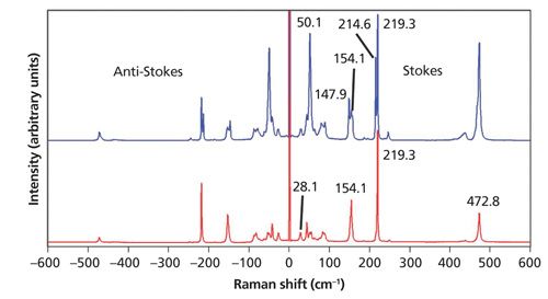
Sulfur is well known for its strong Raman scattering and the low-energy phonons that can be detected if one can get close enough to the laser line. Two spectra of sulfur acquired from different grains from the same sample source are shown in Figure 1. The use of a 532-nm laser with a very narrow line (highly monochromatic) in conjunction with a laser line rejection filter and volume holographic grating notch filter allows one to detect Raman bands as low as 4.0 cm-1 and to detect both the Stokes and anti-Stokes Raman scattering. (All of the low-energy Raman spectra and images reported in this publication were acquired using 532-nm excitation with this configuration.) The lowest energy band detected in the sulfur spectrum is at 28.1 cm-1, much lower than the conventional laser line cutoff. There are several things to notice about the sulfur spectra in Figure 1. The first is that the signal strengths of the anti-Stokes Raman bands grow progressively weaker with greater Raman shift. For example, the strong bands at 219.3 and 472.8 cm-1 in the Stokes spectrum are considerably weaker on the anti-Stokes side. This is because the population of the first excited vibrational state is dependent on the temperature and the difference in energy between the ground and first excited vibrational state. Consequently, the higher the energy of the first excited vibrational state or phonon, the lower the population of that state and the weaker the anti-Stokes Raman scattering will be.
In fact, the ratio of the anti-Stokes to Stokes Raman scattering is entirely dependent on the energy of the vibrational transition and the temperature. The following expression describes the mathematical relationship of the anti-Stokes and Stokes Raman scattering signal strength with temperature and the energy of the vibrational transition

where IAS is the anti-Stokes signal strength, IS is the Stokes signal strength, νl is the laser frequency expressed in terms of wavenumbers (reciprocal centimeters), νv is the vibrational mode frequency, h is Planck’s constant, k is Boltzmann’s constant, and T is the temperature (2). What follows from this expression is that the temperature of a substance can be determined by measuring the Stokes and anti-Stokes Raman scattering. Any pair of anti-Stokes and Stokes Raman bands from the spectrum should suffice because their peak positions are easily identified. However, of those measurable components in the equation above, the Raman signal strength is what most affects the accuracy and precision of temperatures that are derived from the Raman spectrum. Consequently, as we can clearly see from the spectra in Figure 1, the lower the energy of the Raman band the stronger the anti-Stokes signal will be. So, the best anti-Stokes signal-to-noise for temperature determination will be obtained by using bands at the lowest Raman shifts, that is, low-energy phonons.
Crystal Orientation and Molecular Interactions
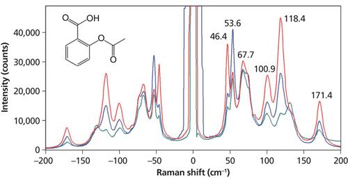
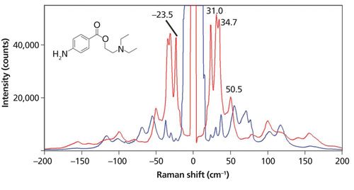
Another important observation to be made of the spectra in Figure 1 is that the relative intensities are significantly different. The spectra were acquired from different sulfur grains oriented differently with respect to the incident laser polarization. No Raman polarization analyzer was used and yet we see substantial spectral differences with crystal orientation. Of course, the low-energy phonons follow the same Raman polarization selection rules that govern the higher energy phonons or internal vibrational modes. The effects of laser polarization with respect to crystal orientation are further demonstrated in the Raman spectra acquired from aspirin and procaine grains shown in Figures 2 and 3, respectively. Both compounds are pharmaceutical ingredients; procaine (C13H20N2O2) is a compound used primarily as a topical anesthetic. The aspirin and procaine spectra were obtained by focusing the 532-nm laser beam with an Olympus 100× microscope objective on different grains from the same source. A cursory examination of the aspirin spectra might lead the uninitiated to incorrectly conclude that the spectra were acquired from different compounds when in fact the grains are simply oriented differently. Regarding the procaine, note how strong the Raman scattering of the external phonons is, specifically the bands at 23.5, 31.0, and 34.7 cm-1. It is well known that the low-energy phonon modes of many organic molecular crystals have very high Raman scattering cross-sections. That is one reason why the pharmaceutical industry finds this region of the Raman spectrum so useful for the differentiation of polymorphs. However, the Raman spectra of procaine very effectively demonstrate the sensitivity of crystal orientation to incident laser polarization, which must be accounted for when using Raman spectroscopy for polymorph characterization. The spectra of sulfur, aspirin, and procaine acquired at different crystal orientations with respect to the incident laser polarization should impress upon the spectroscopist that care must be taken in interpreting low-energy Raman spectra of crystalline grains, particularly if one is using that portion of the Raman spectrum to characterize or differentiate polymorphs. Recalling the previously discussed temperature measurements, the procaine spectra demonstrate the value of using Stokes and anti-Stokes Raman bands of low-energy phonons to determine temperature. The signal-to-noise of the anti-Stokes scattering is very strong, thereby yielding more-accurate temperatures.
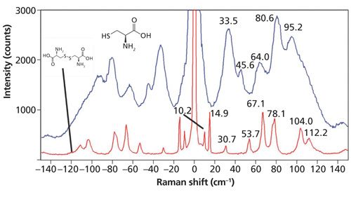
In the introduction we stated that the external vibrational modes are particularly sensitive to molecular interactions and interlayer van der Waals forces. Here we demonstrate that claim through the Raman spectra of cystine and the amino acid cysteine shown in Figure 4. Cystine is the oxidized form of cysteine wherein “the thiol groups of two molecules of cysteine have been oxidized to a disulfide group to provide a covalent cross-linkage between them” (3). Both spectra were acquired from individual grains taken from reagent bottles of the crystalline forms of cystine and cysteine. In spite of the fact that the two compounds are compositionally similar, the low-energy Raman spectra are remarkably different. The cystine Raman bands are very sharp with two bands at 10.2 and 14.9 cm-1 fully resolved. In contrast, the Raman spectrum of cysteine has low-energy bands that are much broader compared to those of cystine. The region from 20 to approximately 130 cm-1 in the cysteine spectrum manifests Raman scattering with no baseline and broad maxima at the positions labeled on the spectrum. The breadth of the low-energy Raman bands indicates strong molecular interactions within the cysteine crystal. In contrast, the cystine Raman spectrum manifests very sharp peaks thereby indicating very weak molecular interactions.
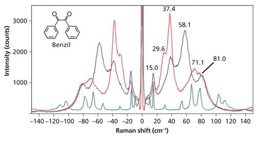
Even though the molecular interactions in a crystalline form are strong and the Raman bands are broad, the spectrum will still manifest a dependence on crystal orientation with respect to the incident laser polarization. Raman spectra of grains at different orientations of the organic compound benzil (C6H5COCOC6H5) taken from the same reagent bottle are shown in Figure 5. The Raman spectrum of benzil was studied decades ago and all the bands observed in Figure 5 have been assigned to external phonons (4). The low-energy Raman spectra of benzil, just like cysteine, have broad bands with no baseline below approximately 110 cm-1. This band structure indicates how strong the molecular interactions are within the benzil crystal. A spectrum of cystine is included in the plot for recognition of bandwidth contrast between that of benzil and that of a crystal with weak molecular interactions. Notwithstanding the strong molecular interactions within the benzil crystal, the crystalline orientational dependence is quite evident. The relative intensities of spectra acquired from different grains from the same reagent bottle oriented differently with respect to the incident laser polarization are significantly different.
Raman Spectroscopy of Few-Layer MoS2 Low-Energy Phonons
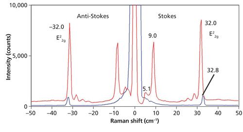
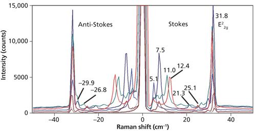
Thus far, the spectra that we have examined have been of bulk crystals. Here we find that Raman spectra of low-energy phonons in so-called two dimensional (2D) crystals such as few-layer MoS2 can be quite revealing about the solid-state structure. The low-energy band structure of 2D crystals vary far more with solid-state structures than do the higher-energy optical phonons. Raman spectra of bulk MoS2 and a few-layer sample acquired with 532 nm excitation are shown in Figure 6. The bulk spectrum consists of the single E22g band at 32.8 cm-1. However, the few-layer MoS2 spectrum consists of the E22g band at 32.0 cm-1, three weak bands just below 30 cm-1, a strong band at 9.0 cm-1, and a Si substrate band at 5.1 cm-1. Examination of multiple few-layer flakes as well as different positions on a single flake reveals a variety of low-energy Raman bands as shown in Figure 7. Note that the E22g band at approximately 32 cm-1 does vary slightly in position and strength but not as significantly as the bands below 30 cm-1. The analysis and interpretation of the low-energy interlayer breathing and shear modes of few-layer MoS2 have been rigorously studied (5–7). For a more detailed discussion of Raman spectroscopy and imaging of higher energy Raman bands of few-layer MoS2, consult the March 2015 issue of Spectroscopy (8).
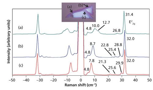
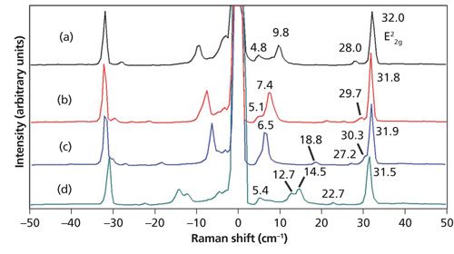
A clear pattern emerges between the appearance of low-energy phonon modes in the Raman spectra of few-layer MoS2 and the location on or color of a particular flake. Spectra acquired from the edge and purple sections of a few-layer MoS2 flake are shown in Figure 8. Note the low-energy bands below the E22g band and their varied Raman shifts at the different positions on the flake; none of these bands appear in the bulk spectrum of MoS2. Furthermore, even when the band structures appear similar as in the spectra from positions (b) and (c), the low-energy phonon peak positions are not identical except for the E22g and Si substrate (4.8 cm-1) bands. The peak positions below the E22g band differ by approximately 1 cm-1 in the spectra from locations (b) and (c). The low-energy Raman spectra of few-layer exfoliated MoS2 flakes reveal a solid-state structural heterogeneity that is not observed in the higher energy phonons.
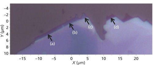
The edges or perimeters of few-layer MoS2 flakes often consist of small (several micrometers) extensions with varying shades of purple and very different low-energy Raman spectra. A reflected light image of one such few-layer flake is shown in Figure 9. The colors of these small extensions of the flake range from deep blue to purple. Raman spectra were acquired at positions labeled (a) through (d) and they are shown in Figure 10. Here, again, we see small shifts in the E22g band but the number and positions of the bands at Raman shifts lower than 32 cm-1 vary more significantly with position. The interpretation of the low-energy Raman spectra in conjunction with the colors of whole few-layer flakes and these edge features should be an intriguing and important area of study. In particular, the application of atomic force microscopy in conjunction with reflected light optical microscopy and low-energy Raman spectroscopy and imaging would be helpful in possibly correlating the color and Raman band structure to the number of MoS2 layers.
Raman Imaging of Few-Layer MoS2 Low-Energy Phonons
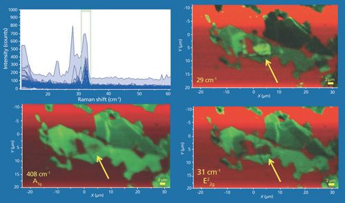
Now that we’ve seen the rich variety of spectra uncovered below the E22g band, with respect to position it seems reasonable to map the few-layer MoS2 flakes to render Raman images of the low-energy phonons. A collection of data from a few-layer MoS2 flake is shown in Figure 11. The Raman data were acquired using 532-nm excitation and a 100× Olympus objective and by moving the stage in 200-nm increments over an area of approximately 55 µm × 30 µm. The Raman images in the lower left, lower right, and upper right frames are rendered using the green color brackets to capture the A1g (not shown), E22g, and 29 cm-1 bands, respectively. The plot on the upper left consists of all of the Raman spectra acquired over the image area. The red color brackets (not shown) surrounded the 520 cm-1 band and so the red color in the Raman images corresponds to the Si substrate. Of course, the A1g, E22g, and 29 cm-1 band images of the few-layer MoS2 appear quite similar; however, there are some subtle but important differences among the three images. For example, observe and compare that portion of the images pointed out by the yellow arrows. Note that in the A1g image the area appears somewhat fuzzy green and the red substrate is partially visible, perhaps indicating a thin layer of MoS2. That same area in the E22g image appears completely red suggesting the absence of MoS2 at that location based on the E22gg image alone. However, the 29 cm-1 band image shows that area to be among the brightest green, thereby confirming the presence of MoS2. The variation of the green contrast among the different images may indicate a spatial variation of thickness within individual flakes. The important takeaway point from these images is that a Raman image of one peak position alone is insufficient to adequately reveal the spatially varying solid-state structure of the few-layer MoS2 flakes.
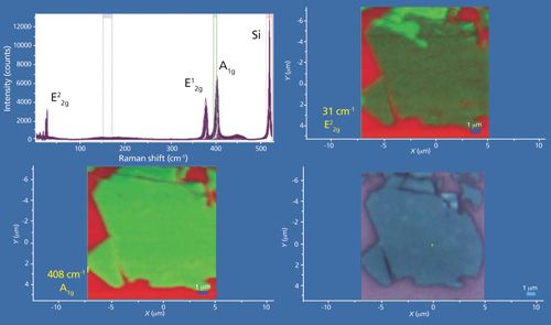
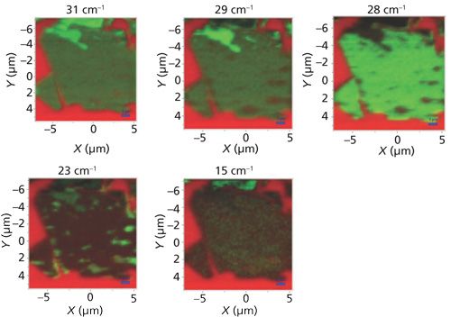
Another collection of data from a few-layer MoS2 flake is shown in Figure 12. Here again, the Raman data were acquired using 532-nm excitation and a 100× Olympus objective and by moving the stage in 200-nm increments over an area of approximately 12 µm × 12 µm. A reflected white light image of the flake appears in the lower right-hand corner and Raman A1g and E22g images of the same area appear in the lower left-hand and upper right-hand corners, respectively. The bright red areas indicate a bare Si substrate. The plot in the upper left consists of all of the Raman spectra acquired over the image area. The Raman images in the lower left and upper right frames are rendered using the green color brackets to capture the A1g and E22g bands, respectively. The few-layer MoS2 flake would appear to be uniform based upon the reflected white light image, and the uniform A1g image supports that interpretation. However, the E22g image in the upper right hand corner reveals clear heterogeneity with the top portion of the flake yielding the most intense E22g Raman scattering.
The differences between the A1g and E22g Raman images reminds us that depending upon the complexity of the material, rendering an image based on a single band can sometimes provide only a single perspective and not the whole picture. In fact, images of the same flake based on the low-energy phonon modes between 15 cm-1 and 31 cm-1 reveal just how heterogeneous this few-layer flake is despite its appearance in the A1g and reflected white light images. A series of Raman images at 31, 29, 28, 23, and 15 cm-1 of this same few-layer flake is shown in Figure 13. All of the images are on different intensity scales, normalized to the maximum and minimum signal strength of that particular Raman band. Note how significantly different the images appear even though they are separated by only a small Raman shift. At 29 cm-1 a portion of the top bright region in the 31 cm-1 Raman image has grown dim and “holes” revealing the red Si substrate begin to appear on the right and bottom portions of the flake. At 28 cm-1 the top formerly bright green region has grown dark, the holes revealing the red Si substrate have grown clearer, and the rest of the flake is uniformly bright green. Next, the 23 cm-1 image appears to be almost the inverse of that at 28 cm-1; the formerly red holes now appear the brightest green because of MoS2 Raman scattering. Finally, the 15 cm-1 Raman image shows strong contrast with the top portion of the flake appearing bright green and the remainder very dim because of the weakness or absence of scattering at that Raman shift.
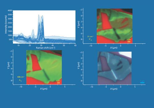
Continuing with our theme that multiple perspectives provide a more complete image, another collection of data from a few-layer MoS2 flake is shown in Figure 14. The Raman data were acquired using 532-nm excitation and a 100× Olympus objective and by moving the stage in 200-nm increments over an area of approximately 11 µm × 11 µm. A reflected white light image of the flake appears in the lower right hand corner and Raman A1g and E22g images of the same area appear in the lower left-hand and upper right-hand corners, respectively. The bright red areas indicate a bare Si substrate. The plot on the upper left consists of all of the Raman spectra acquired over the image area. The Raman images in the lower left and upper right frames are rendered using the green color brackets to capture the A1g (not shown) and E22g bands, respectively. We see that once again the A1g and E22g images are similar but not identical. The green contrast of the strongest to the weakest Raman scattering in the two images are different; the A1g Raman image appears relatively more uniform than that of the E22g image. Interestingly, both images show dark lines (weak Raman scattering) where two near vertical white lines appear in the reflected white light image. Comparison of the A1g and E22g images informs us that the few-layer MoS2 solid-state structure is not uniform. If the flake were to be uniformly oriented and consist of the same number of layers, the ratio of the A1g and E22g band strengths would be constant and the normalized Raman images would appear the same.
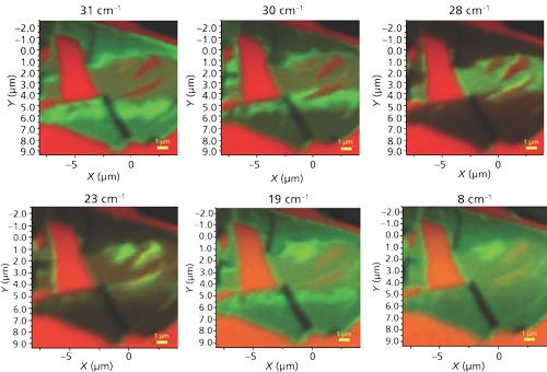
A series of low-energy Raman images at 31, 30, 28, 23, 19, and 8 cm-1 of this same few-layer MoS2 flake is shown in Figure 15. All of the images are on different intensity scales, normalized to the maximum and minimum signal strength. Note how significantly different the images appear even though they are separated by only a small Raman shift. Again we see what appear to be “holes” in the MoS2 flake, the red areas within the flake on the right side of the 31, 30, and 28 cm-1 Raman images. However, those same red holes appear the most green from MoS2 Raman scattering in the 23 cm-1 Raman image. In spite of the larger variability of the MoS2 Raman scattering in these images, common to all of these Raman images are the dark near vertical lines that correspond to the near vertical white lines that appear in the reflected white light image.
A convenient summary of the patterns that emerge from Raman imaging of low- and high-energy phonons of few-layer MoS2 is represented in Figure 16. The Raman data were acquired using 532-nm excitation and a 100× Olympus objective and by moving the stage in 200-nm increments over an area of approximately 11 µm × 15 µm. A reflected white light image of the flake appears in the lower right-hand corner and Raman A1g and 8 cm-1 images of the same area appear in the lower left-hand and upper right-hand corners, respectively. The bright red areas indicate a bare Si substrate. The plot in the upper left consists of all of the Raman spectra acquired over the image area. The Raman images in the lower left and upper right frames are rendered using the green color brackets to capture the A1g and 8 cm-1 bands, respectively. The A1g image bears what we may call an inverse correspondence to the reflected white light image, that is, the brighter and darker areas in the reflected light image manifest weak and strong Raman scattering in the A1g image, respectively. The inverse correspondence of the reflected light and A1g and E22g images is really quite striking and typical of all of the A1g and E22g images that we have acquired of few-layer MoS2 exfoliated flakes. The 8 cm-1 Raman image also shows an inverse correspondence, but not to the contrast level of the A1g image. Nevertheless, the darkest areas of the reflected light image do correspond to the brightest regions in the 8 cm-1 Raman image.
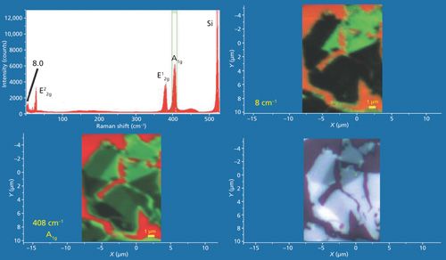
Images of the high- and low-energy MoS2 Raman bands correspond to the internal vibrational modes and the shear and interlayer breathing modes, respectively. Altogether, they provide multiple perspectives to form a more complete image of 2D crystals such as few-layer MoS2.
Conclusions
Raman spectra of low-energy phonons are dependent on the crystal orientation with respect to the incident laser polarization. The spectra of sulfur, aspirin, and procaine acquired at different crystal orientations with respect to the incident laser polarization should impress upon the spectroscopist that care must be taken in interpreting low-energy Raman spectra of crystalline grains, particularly if one is using that portion of the Raman spectrum to characterize or differentiate polymorphs. The sensitivity of the external modes to molecular interactions, such as hydrogen bonding or even the weaker van der Waals forces, between molecular or atomic layers was demonstrated.
There is a clear pattern between the appearance of low-energy phonon modes in the Raman spectra of few-layer MoS2 and the location on or color of a particular flake. The interpretation of the low-energy Raman spectra in conjunction with the colors of whole few-layer flakes and the edge features should be an intriguing and important area of study. In particular, the application of atomic force microscopy in conjunction with reflected light optical microscopy and low-energy Raman spectroscopy and imaging would be helpful in possibly correlating the color and Raman band structure to the number of MoS2 layers.
We discussed the Raman spectroscopy of low-energy phonons and demonstrated the practicality of imaging them for the characterization of 2D crystals. The important takeaway point from these images is that a Raman image of one peak position alone is insufficient to adequately reveal the spatially varying solid-state structure of the few-layer MoS2 flakes. Images rendered from the spatially varying signal strengths of the high- and low-energy phonon modes of few-layer MoS2 correspond to the internal vibrational modes and the shear and interlayer breathing modes, respectively. A single Raman image of any of these modes is insufficient to reveal the solid state structure. Viewing Raman images of all the modes allows one to form a more complete understanding of 2D crystal structures such as few-layer MoS2.
References
(1) P.M.A. Sherwood, Vibrational Spectroscopy of Solids (Cambridge University Press, London, 1972), pp. 1–4.
(2) S.D. McGrane, D.S Moore, P.M. Goodwin, and D.M. Dattelbaum, Appl. Spec.68, 12791–1288 (2014).
(3) A. Lehninger, Biochemistry (Worth Publishers, New York, 1979), p. 72.
(4) R. Claus, H.H. Hacker, H.W. Schrötter, and J. Brandmüller, Phys. Rev.187, 11281–1131(1969).
(5) Y. Zhao, X. Luo, H. Li, J. Zhang, P.T. Araujo, C.K. Gan, J. Wu, H. Zhang, S.Y. Quek, M.S. Dresselhaus, and Q. Xiong, Nano Lett.13, 10071–1015 (2013).
(6) X. Zhang, W.P. Han, J.B. Wu, S. Milana, Y. Lu, Q.Q. Li, A.C. Ferrari, and P.H. Tan, Phys. Res. B87, 115413 (2013).
(7) N. Scheuschner, R. Gillen, M. Staiger, and J. Maultzsch, Phys Rev B91, 235409 (2015).
(8) D. Tuschel, Spectroscopy30(3), 141–29 (2015).

David Tuschelis a Raman applications manager at Horiba Scientific, in Edison, New Jersey, where he works with Fran Adar. David is sharing authorship of this column with Fran. He can be reached at: david.tuschel@horiba.com
.

A Proposal for the Origin of the Near-Ubiquitous Fluorescence in Raman Spectra
February 14th 2025In this column, I describe what I believe may be the origin of this fluorescence emission and support my conjecture with some measurements of polycyclic aromatic hydrocarbons (PAHs). Understanding the origin of these interfering backgrounds may enable you to design experiments with less interference, avoid the laser illuminations that make things worse, or both.
Leveraging Electrochemical Impedance Spectroscopy for Lithium-Ion Battery Temperature Prediction
January 17th 2025Researchers have developed a non-invasive, highly accurate method using electrochemical impedance spectroscopy (EIS) to predict the temperature of lithium-ion batteries in real time.
Agilent Presents Awards to 3 Professors for Lithium-Ion Battery Research
January 15th 2025The Solutions Innovation Research awards were presented to Professor Anders Bentien of Aarhus University, Professor Walter Gössler of the University of Graz, and Professor Gregory Offer of Imperial College London.