In Situ Raman Spectroscopy Monitoring of the Reaction of Sulfur Trioxide with Polyethylene Fibers in Chlorinated Solvents
Spectroscopy
The apparent reaction kinetics between SO3 and polyethylene are investigated in various halogenated solvents using in situ Raman spectroscopy with an immersion Raman probe, demonstrating the power of in situ Raman spectroscopy to monitor hazardous reactions.
Sulfur trioxide (SO3) is a highly reactive oxidant, and its reactions with polyethylene fibers in chlorinated solvents can be used to functionalize and stabilize the polyethylene fibers for subsequent carbonization to produce carbon fiber. In this study, the apparent reaction kinetics between SO3 and polyethylene were investigated in various halogenated solvents using in situ Raman spectroscopy with an immersion Raman probe. This work demonstrates the power of in situ Raman spectroscopy to monitor hazardous reactions, and the results show that both solvent and polyethylene properties have a large influence on the reaction kinetics.
Carbon fiber is being used in an increasingly wider range of applications, such as in light structural materials and polymer composites (1–5). Polyethylene (PE) has been suggested to be a lower-cost precursor material to carbon fibers than the traditional precursor polyacrylonitrile (PAN). Polyethylene fibers can be converted to carbon fibers by a stabilization step (by sulfonation) followed by a carbonization step (1,6–10). Sulfur trioxide (SO3) in halogenated solution was proposed to be an effective way for the stabilization and sulfonation of polyethylene (11).
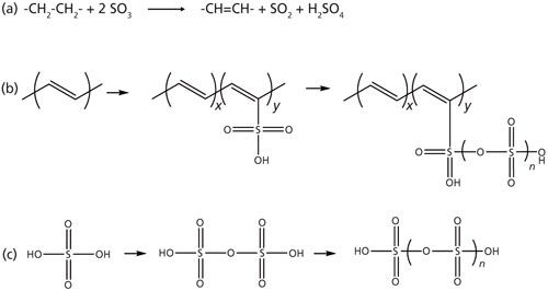
The main hypothesized sulfonation reaction is shown in Figure 1a. Various side reactions can also occur as shown in Figures 1b and 1c, and will sequester SO3 that is then unavailable for the main sulfonation reaction (Figure 1a). Knowledge of the SO3 solution concentration is of vital importance because it affects the reaction rate and process economics. However, the high reactivity of SO3 makes this reaction difficult to monitor by off-line analysis, because SO3 readily reacts with water to form sulfuric acid (H2SO4), and traditional titration methods cannot differentiate between SO3 and H2SO4. Raman spectroscopy was found to be a powerful tool that allowed in situ monitoring of key reaction species in the solution phase such as SO3 and sulfur dioxide (SO2).
Figure 1: Sulfonation reactions: (a) the hypothesized main reaction, and (b, c) potential side reactions.
Raman spectroscopy has previously been applied to study the molecular structure and oligomerization of SO3 (12,13) and SO2 (14–16) Furthermore, a Raman method has been developed to determine the concentration of SO2 and SO3 in the gas phase. This article describes a calibration method that was first developed to quantify SO3 and SO2 in halogenated solvents based on a classical least squares (CLS) fit of Raman spectra. This calibration was then applied to monitor the SO3 reaction with polyethylene fibers with a goal to understand the influence of various experimental variables such as the polyethylene density, branching, and crystallinity (three properties interrelated to each other), and the reaction-solvent type. Scanning electron microscopy and X-ray energy-dispersive spectroscopy (SEM-XEDS) was used as a complementary tool to directly obtain the radial sulfur distribution from thin sections of polyethylene fibers as a function of sulfonation time.
Experimental
Reagents and Materials
Polyethylene fibers were prepared from three types of Dow proprietary polyethylene resins with different crystallinity and density. These three fibers will be referred to by their densities, with PE-950, PE-926, and PE-917 having a density of 0.950, 0.926, and 0.917 g/mL, respectively. Polyethylene fibers were melt spun using a Hills Inc. commercial melt spinning line. The resulting fibers were ~20 µm in diameter with a tenacity of ~2 g/denier. SO3 was received from Aldrich in 40-g lots in solid form in glass bottles. To be able to transfer the SO3 in a safe fashion, the bottles were stored in a low-temperature oven in a vented hood at 37–39 °C with the appropriate high-temperature cut-off safety features (monomeric SO3 boils at 45 °C). When SO3 is in its liquid form, it is easily manipulated in a well-vented hood (significant fuming is always evident) for dissolution into inert solvents. SO3 is exceedingly hazardous: inhalation or contact with skin results immediately in severe burns.
Several halogenated solvents were investigated in this study: 1,2-dichloroethane (ClCH2CH2Cl, DCE), methylene chloride (CH2Cl2), chloroform (CHCl3), carbon tetrachloride (CCl4), and 1,1,2,2-tetrachloroethane (CHCl2CHCl2). All solvents were acquired from Aldrich and were used as received.
Raman Spectroscopy
A Kaiser RXN1 Raman spectrometer with 785-nm laser excitation was used with a fiber-optic probe. A Kaiser 0.25-in. diameter short-focus immersion optic was used to collect signals in the backscattering geometry. The signal was dispersed by a grating and projected onto a charge-coupled device (CCD) camera for spectral collection. The body of the immersion optic was made of Hastelloy C alloy and the tip of it was sealed with a sapphire window. No corrosion was observed even after multiday experiments. Typical laser power ranged from 100 mW to 400 mW, and typical spectral acquisition conditions were 1-s exposure time with 10 accumulations and with the cosmic ray filter on (20 s per spectrum). In some reactions, strong fluorescence was observed and the exposure time was shortened correspondingly. All experiments were carried out at room temperature (unless otherwise specified) with stirring inside a customized glass reactor. Care was taken to ensure that the laser beam was not focused onto a sulfonated fiber; otherwise overwhelmingly strong fluorescence would result.
Data Analysis
Spectral visualization was performed using OMNIC 8.2 software (Thermo Fisher Scientific Inc.). Because of spectral overlapping, quantitative analysis was carried out using a CLS algorithm as implemented in MATLAB. Details of the CLS method can be found elsewhere (17–19).
Results and Discussion
The polyethylene fiber surface turned brown and then black during its reaction with SO3, and the solution remained clear. The surface color change is believed to be mostly due to the formation of the conjugated double bond system shown in Figure 1a. Attempts to collect Raman spectra from the fiber surface were made but strong fluorescence overwhelmed the Raman signal. As a result, all the Raman spectra were collected from the solution-phase composition change to monitor the reaction progress. The majority of the reactions were carried out in DCE. Several other halogenated solvents were tested. Some of them showed a fast reaction with SO3, and others showed negligible reaction. Several other inert solvents were also tested as reaction solvents. The calibration results obtained in the DCE solution are discussed below. As a complementary tool, SEM-XEDS was used to directly measure the sulfur distribution on the cross sections of partially sulfonated polyethylene fibers, and those results are also discussed below.
Calibration Experiments
A quantitative method was needed to monitor the SO3 consumption and SO2 generation in the solution phase during the polyethylene and SO3 reaction. Standard spectra of pure DCE solvent, 3 wt% SO2 in DCE, and 3.7 wt% SO3 in DCE are shown in Figure 2. At such concentrations, SO3 and SO2 exist mostly in their free monomer form as indicated by the strong 1066 cm-1 peak from the υ1 mode of SO3, and the strong 1145 cm-1 peak from the υ1 mode of SO2 (16,20–22). DCE was the initial solvent selected for this study because of its compatibility with SO3. Its Raman spectrum is consistent with that previously reported (23) and had a peak at 1054 cm-1 that interfered with the SO3 1066 cm-1 peak, and also another peak at 1145 cm-1 that interfered with the SO2 1145 cm-1 peak.
Figure 2: Standard Raman spectra of DCE (purple), 3 wt% SO2 DCE solution (green), and 3.7 wt% SO3 DCE solution (red). The inset plot shows the calibration for SO3 in DCE; a linear correlation is found for the low concentration range between the SO3/DCE weight ratio and the CLS response ratio.
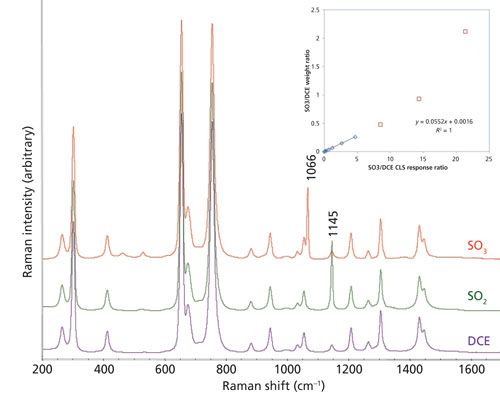
Because of the severe spectral interference from DCE, a CLS model was developed to deconvolute the spectra for quantitation of SO3 and SO2 concentrations. The CLS algorithm uses a linear combination of all the pure component spectra to reproduce a reaction spectrum by minimizing the sum of squares of the differences (19,24). The CLS response, also referred to as the weight, is proportional to the concentration of the corresponding species. The spectral range between 1000 and 1250 cm-1 was used for the CLS analysis with the spectra of three pure components: DCE, and the SO3 and SO2 solution spectra after subtraction of solvent contributions. For the quantitation of SO3 and SO2, their CLS responses were normalized by the DCE solvent CLS response. The normalized CLS response ratios were found to be linearly proportional to the weight ratio of SO3 and SO2 to DCE solvent within a certain concentration range (<10 wt%). The reason for such a limited concentration range is that in addition to free monomer, SO3 may exist in forms such as dimer, trimer, tetramer, or polymers, and each form has different Raman features (13). An example of such a correlation is shown in the inset plot in Figure 2. When the SO3 concentration was sufficiently high, a nonlinear correlation behavior was observed because of dimer and oligomer formation.
Raman Monitoring of the SO3 Reaction with Polyethylene
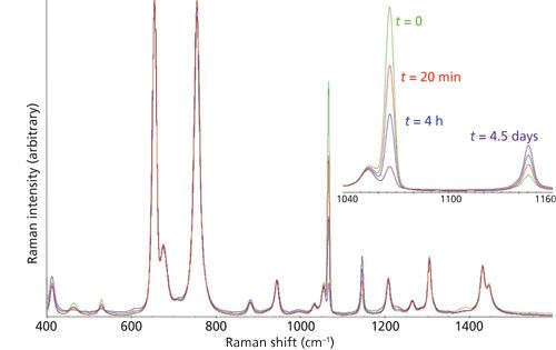
The solution-phase SO3 and SO2 concentrations can be determined using the method described above. Raman spectra collected as a function of reaction time could thus be used to monitor the sulfonation reaction of polyethylene fibers. Representative reaction spectra from an example reaction are shown in Figure 3. In this experiment, 106 mg of PE-926 fiber (0.025 g/m) was reacted with 1.75 g of SO3 dissolved in 14.54 g of DCE. Upon contact, the fiber surface quickly darkened in color (25), and the solution remained mostly colorless. The consumption of SO3 and generation of SO2 can be seen clearly in the inset spectra in Figure 3. The CLS model and calibration were applied to the reaction spectra so that the concentrations of SO3 and SO2 could be calculated. Based on the main reaction shown in Figure 1a, the amount of polyethylene should lead to the consumption of only approximately 35% of the starting SO3. The experimentally observed SO3 consumption was much higher, indicating that a significant consumption resulting from side reactions occurred. The observed concentration increase of SO2 was also greater than the 1.5% concentration expected if only the main reaction shown in Figure 1a was operable. Although the overconsumption of SO3 readily could be explained by the side reactions (Figures 1b and 1c), the reaction mechanism responsible for overgeneration of SO2 remains to be studied.
Figure 3: Representative spectra from in situ Raman monitoring of the solution-phase reaction.
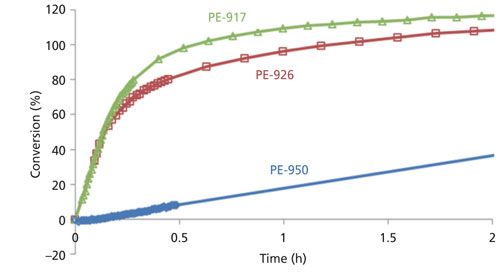
With such a method, it became possible to gain a deeper understanding of the influence on the reaction kinetics of various key process variables such as crystallinity, fiber diameter, and solvent type. To further aid the comparison of reaction kinetics, the SO3 and SO2 concentrations were converted to extent of conversion, assuming only the main reaction shown in Figure 1a occurred. The conversion can then be calculated based on the amount of polyethylene, which was always the limiting reagent (that is, the number of moles of SO3 is always more than twice that of -CH2- repeating units in polyethylene). Figure 4 compares the reaction conversion for three experiments with similar conditions but with three different polyethylene fibers (with similar diameter) in terms of SO2 production. It is obvious that the PE-950 fiber, with the highest crystallinity, exhibited the slowest reaction, and a reaction with an overall lower extent was noted when the profiles plateaued.
Figure 4: SO2 formation kinetics observed for three types of polyethylene fibers.
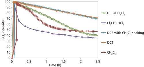
Similarly, the influence of solvent type on the reaction kinetics was investigated. Only solvents that showed negligible reactivity toward SO3 (see next section) were used. Five reactions using the same type of polyethylene fiber and a similar starting amount of SO3 and polyethylene were carried out in various inert solvents (see the next section). Figure 5 compares the percentage of SO3 remaining (after normalizing against the starting concentration). The type of solvent appeared to have a large influence on the reaction kinetics. The same type of methodology was used as outlined above for the SO3–DCE mixture system to develop CLS models for the SO3 quantitation for each solvent system (or using peak area if a solvent spectrum did not interfere with the SO3 1145 cm-1 peak), but the details are not shown here. In all five reactions, the SO3 solution was added into the reactor shortly after time 0. The consumption rate appeared to be the slowest with DCE as the solvent. When methylene chloride was used as the solvent, a significantly faster reaction rate was observed. It was hypothesized that such a rate increase might be a result of partial swelling by methylene chloride (26,27). To test this hypothesis, another experiment was performed by pre-immersing polyethylene fibers in methylene chloride and then immediately carrying out the reaction with SO3 in a DCE solution. Almost identical reaction kinetics were observed, disproving the swelling hypothesis. In another experiment, a mixture solvent with 1:1 (w/w) DCE and methylene chloride was used; the initial kinetics profile resides between that of the pure DCE and of pure methylene chloride. Among all the solvents tested, 1,1,2,2-tetrachloroethane appeared to facilitate the reaction most effectively.
Figure 5: Reaction kinetics observed for the same polyethylene fiber reacting with SO3 in various solvents.
SEM-XEDS Characterization of Sulfonated Fiber Cross-Sections
SEM-XEDS analysis was used to directly measure the radial sulfur distribution within the polyethylene fiber as a way to monitor the extent of sulfonation with time. This information is less quantitative but complementary to the solution concentration provided by the Raman results. Fibers withdrawn after various lengths of sulfonation time were immediately placed into a water bath to quench the reaction and then were prepped for analysis.
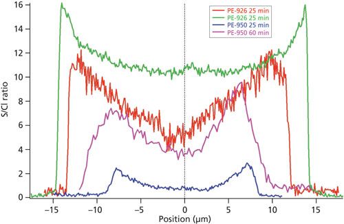
Figure 6 shows a comparison of radial distributions of S/Cl ratio for PE-926 and PE-950 fibers sulfonated for 25 and 60 min after immersion in a 1.58 M solution of SO3 in DCE. The slower rate of sulfur concentration increase in the PE-950 fiber relative to the PE-926 fiber is clearly shown, suggesting that the sulfonation reactions for PE-950 are slower. In fact, the overall magnitude of sulfur in the PE-926 fiber after only 25 min was greater than that observed in the PE-950 fiber after 60 min of sulfonation. These observations are consistent with the differences in reaction rates observed via Raman spectroscopy as shown in Figure 4. These results clearly demonstrated that the reaction kinetics between SO3 and polyethylene are sensitive to the polyethylene material’s density, branching, and crystallinity, which are three properties closely related to each other.
Figure 6: S/Cl profiles of PE-926 and PE-950 fibers after 25 and 60 min in a 1.58 M solution of SO3 in DCE.
Conclusion
In situ Raman spectroscopy was used to monitor the SO3 consumption and SO2 generation in DCE and other chlorinated solvents during polyethylene and SO3 reactions. CLS analysis was used to quantify the spectral contribution of SO3 and SO2 in the presence of strong solvent interference. The reaction kinetics data could thus be obtained from the solution-phase measurements when different types of polyethylene reacted with SO3 in various solvents. It was found that solvent type and polyethylene crystallinity, density, and branching have a substantial influence on the reaction kinetics. The exact mechanism behind such influences remains to be investigated and is likely related to diffusion and mass transfer limitation. Complementary SEM-XEDS measurements of sulfur distribution within the polyethylene fiber as a function of time were also obtained to further confirm these results. This study clearly demonstrates the power of in situ Raman spectroscopy to monitor these hazardous reactions.
References
- E. Frank, F. Hermanutz, and M.R. Buchmeiser, Macromol. Mater. Eng. 297(6), 493–501 (2012).
- E. Thostenson, W. Li, D. Wang, Z. Ren, and T. Chou, J. Appl. Phys. 91(9), 6034–6037 (2002).
- W. Jonda, “Lightweight structural part formed of carbon fiber-reinforced plastic” (Google Patents, 1978).
- M. Tavakkolizadeh and H. Saadatmanesh, J. Struct. Eng. 129(1), 30–40 (2003).
- D. Chung, Carbon Fiber Composites (Butterworth-Heinemann, Oxford, UK, 2012).
- J.M. Younker, T. Saito, M.A. Hunt, A.K. Naskar, and A. Beste, J. Am. Chem. Soc.135(16), 6130–6141 (2013).
- J. Ihata, J. Polym. Sci., Part A: Polym. Chem.26(1), 167–176 (1988).
- A.R. Postema, H. De Groot, and A.J. Pennings, J. Mater. Sci. 25(10), 4216–4222 (1990).
- X. Huang, Materials2(4), 2369 (2009).
- S. Horikiri, J. Iseki, and M. Minobe, “Process for production of carbon fiber,” Patent US4070446 A, 1978.
- J.T. Patton, B.E. Barton, M.T. Bernius, X. Chen, E.J. Hukkanen, C.A. Rhoton, and Z. Lysenko, “Processes for preparing carbon fibers using sulfur trioxide in a halogenated solvent,” Patent WO2014011462 A1, 2013.
- S.-Y. Tang and C.W. Brown, J. Raman Spectrosc. 3(4), 387–390 (1975).
- R.J. Gillespie and E.A. Robinson, Can. J. Chem. 40(4), 658–674 (1962).
- R.G. Dickinson and S.S. West, Phys. Rev.35(9), 1126–1127 (1930).
- H. Gerding and J.W. Ypenburg, Recl. Trav. Chim. Pays-Bas86(4), 458–462 (1967).
- Y. Song, Z. Liu, H.-K. Mao, R.J. Hemley, and D.R. Herschbach, J. Chem. Phys.122(17), 174511 (2005).
- D.M. Haaland and R.G. Easterling, Appl. Spectrosc. 36(6), 665–673 (1982).
- D.M. Haaland, R.G. Easterling, and D.A. Vopicka, Appl. Spectrosc. 39(1), 73–84 (1985).
- D.M. Haaland and R.G. Easterling, Appl. Spectrosc. 34(5), 539–548 (1980).
- R.A. Nyquist and R.O. Kagel, Handbook of Infrared and Raman Spectra of Inorganic Compounds and Organic Salts: Infrared Spectra of Inorganic Compounds (Academic Press, Cambridge, Massachusetts, 2012).
- E.T.H. Chrysostom, N. Vulpanovici, T. Masiello, J. Barber, J.W. Nibler, A. Weber, A. Maki, and T.A. Blake, J. Mol. Spectrosc. 210(2), 233–239 (2001).
- A.J. Dorney, A.R. Hoy, and I.M. Mills, J. Mol. Spectrosc.45(2), 253–260 (1973).
- S. Mizushima, T. Shimanouchi, I. Harada, Y. Abe, and H. Takeuchi, Can. J. Phys. 53(19), 2085–2094 (1975).
- K.R. Beebe, R.J. Pell, and M.B. Seasholtz, Chemometrics: A Practical Guide (Wiley-Interscience, Secaucus, New Jersey, 1998).
- D. Fischer and H.H. Eysel, J. Appl. Polym. Sci. 52(4), 545–548 (1994).
- A. Peterlin, J.L. Williams, and V. Stannett, J. Polym. Sci. A Polym. Phys. 5(5), 957–972 (1967).
- J.L. Williams and A. Peterlin, J. Polym. Sci. A Polym. Phys. 9(8), 1483–1494 (1971).
Xiaoyun Chen, Jui-Ching Lin, and Michael Behr are with Analytical Sciences at The Dow Chemical Company in Midland, Michigan. Jasson Patton, Bryan Barton, and Zenon Lysenko work in the organic polymer and organometallic group at The Dow Chemical Company. Direct correspondence to: xchen4@dow.com

AI-Powered SERS Spectroscopy Breakthrough Boosts Safety of Medicinal Food Products
April 16th 2025A new deep learning-enhanced spectroscopic platform—SERSome—developed by researchers in China and Finland, identifies medicinal and edible homologs (MEHs) with 98% accuracy. This innovation could revolutionize safety and quality control in the growing MEH market.
New Raman Spectroscopy Method Enhances Real-Time Monitoring Across Fermentation Processes
April 15th 2025Researchers at Delft University of Technology have developed a novel method using single compound spectra to enhance the transferability and accuracy of Raman spectroscopy models for real-time fermentation monitoring.
Nanometer-Scale Studies Using Tip Enhanced Raman Spectroscopy
February 8th 2013Volker Deckert, the winner of the 2013 Charles Mann Award, is advancing the use of tip enhanced Raman spectroscopy (TERS) to push the lateral resolution of vibrational spectroscopy well below the Abbe limit, to achieve single-molecule sensitivity. Because the tip can be moved with sub-nanometer precision, structural information with unmatched spatial resolution can be achieved without the need of specific labels.