Lenses
In the last installment of this column, I discussed prisms. In this installment, we will consider their curved cousins.

A lens is an optical element having axial symmetry and at least one curved surface whose function is to converge or diverge light. The word lens comes from the genus name of the lentil (Lens culinaris), whose shape the common lens mimics. A simple lens is composed of one piece of material, while a compound lens has more than one piece of material, which can be desirable for several reasons.

David W. Ball
A lens must have at least one curved surface, which usually has the shape of an arc of a sphere (hence, called a spherical lens). Having said that, there are several combinations of curved and uncurved (flat) surfaces that can make a lens. Both surfaces can be convex, making a convex lens. One surface can be convex and the other flat, making a plano-convex lens. One side can be convex and the other concave; depending upon which surface has the greater curvature, the lens can be either positive meniscus or negative meniscus. If one side is flat and the other concave, the lens is plano-concave. A biconcave lens has both sides concave. These possibilities are shown in Figure 1. Lenses can have surfaces that are arcs of different curves, like parabolas or hyperbolas. Here, we will focus on just the spherical convex and biconcave lenses.

Figure 1
Convex Lenses
Likely the most recognizable lens, a convex lens acts to converge light. Parallel rays of light entering a lens will all meet at one point on the other side of the lens. The distance between the center of the lens and this meeting point is called the focal length (Figure 2). For a thin lens (in which the thickness of the lens is negligible compared to the radius of curvatures), the focal length can be determined by the curvature of the two sides of the lens. If the radii of curvature of the two surfaces are r1 and r2 and the index of refraction of the lens material is n, then the focal length f is related to these quantities by the equation

In determining the focal length, it is important to observe the proper convention for the signs of r1 and r2: for the first surface, r1 is positive for convex surfaces and negative for concave surfaces, while for r2, the sign is negative for convex surfaces and positive for concave surfaces.
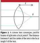
Figure 2
If light striking a point of an object farther than the focal length on one side of a thin convex lens passes through the lens, the light from that point will converge onto a point on the other side of the lens. Light from all points of an object thus focuses on a similar set of points on the opposite side of the lens; we say an image of the object is formed. This is shown in Figure 3a. In this case, the image is referred to as a real image; a screen placed at the position of the image will show a replication of the original object, which is the basis of photography. For a thin convex lens having focal length f, the relationship between the distance of the object to the lens dobj and the distance of the image to the lens dim is

This expression is called the thin lens formula. By convention, dobj and dim are both positive numbers.

Figure 3
If the object is inside the focal length, then light rays emanating from a point do not come to a focus on the other side of the lens, but rather, they diverge. This is shown by the colored arrows in Figure 3b. Projecting the diverging light rays back to their focus, we note that the image we see, a virtual image, is larger than the original object. As such, in this circumstance, a convex lens provides magnification of objects. The formula for calculating the magnifying power M of a lens in this circumstance is

where dim is now negative. Magnifying glasses, for example, work on this principle.
Concave Lenses
If a lens is concave, parallel light coming into it is diffracted away from the axis of symmetry: it is a diverging lens (Figure 4). The parallel light appears to be coming from a focus F that is behind the lens, which is described as having a negative focal length f.
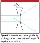
Figure 4
Concave lenses also can be used with images, but in these cases, the images will always be virtual and will be smaller than the original image (minification). Figure 5 illustrates how light rays from a point of an object are affected by the lens.
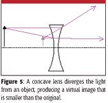
Figure 5
Meniscus lenses behave overall like the surface that has the smaller (that is, steeper) radius of curvature. Thus, negative meniscus lenses behave overall like concave lenses, while positive meniscus lenses behave like convex lenses.
Other Lenses
A cylindrical lens is a lens that focuses parallel light into a line rather than a point. Typically, it has one flat surface and one curved surface, mimicking the surface of a cylinder (Figure 6a). Aspheric lenses are lenses whose curved surface does not follow a spherical arc (Figure 6b). A compound lens is composed of more than one lens, usually of different types or materials (Figure 6c). The individual lenses either are glued together with Canada balsam or epoxy or are mounted sturdily with an air gap in between them.
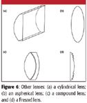
Figure 6
A very interesting lens is the Fresnel lens (Figure 6d), named after the French scientist Augustin-Jean Fresnel (frey-NELL). In a Fresnel lens, each concentric segment (called a Fresnel zone) has a curved surface with the same radius of curvature, but is offset inward at certain radii. This allows the construction of larger lenses without using substantially more material (compare the size of Figure 6d with the plano-convex lens in Figure 1), although early Fresnel lenses were made of multiple individual components and not a single piece. Because the lens was thinner, attenuation of light due to lens material was much less, allowing for brighter light intensity. Fresnel lenses found particular application in lighthouses, where their increased output allowed ships to see them from farther distances.
Problems with or Limitations of Lenses
Despite the equations given earlier and the figures presented now, lenses are not perfect. They present certain imperfections that either limit their usefulness or require some sort of correction to improve their function.
There are several types of aberration. Spherical aberration arises from the fact that a spherical surface is not the ideal surface needed to focus all parallel light to a sharp focus. Generally speaking, the farther away from the lens axis, the closer the light is focused (Figure 7a). The result is a "focus" that occupies a finite distance from the lens. Chromatic aberration is caused by the fact that virtually all lens materials refract light of different color by different amounts. As such, light of different colors will focus in slightly different places, and not only will the focus occupy a different distance from the lens, each position will highlight a different wavelength or frequency of light (Figure 7b). Coma (or comatic aberration) is a type of aberration in which light rays come in at an angle to the optical axis. When this occurs, light entering the lens at different distances from the optical axis converges at different points on a focal plane (Figure 7c). If the lens is circular, the focused light marks out a circle of points for each distance from the axis, with the circle getting larger and dimmer as the distance from the optical axis increases. Because the resulting image resembles a comet, the name for this phenomenon derives from the same Latin root.

Figure 7
Astigmatism is an effect seen when, for a circular lens, focus in one axis is different than the focus in the perpendicular axis. Although we commonly hear about astigmatism when it comes to eyes, optical lenses also can suffer from astigmatism.
Diffraction limits are one ultimate limitation of lenses. Because lenses are of finite size, they essentially act as a "hole" that light rays pass through. We know from experiments on light going through an aperture that the light waves will diffract, which changes the direction of the light's propagation. As such, an image will not be infinitely sharp, but will experience some amount of blurriness. If we assume that the light waves impinging on the lens are parallel, then the light experiences what is called Fraunhofer diffraction. This diffraction causes a point source to be imaged as a finite-sized image called an Airy disk (Figure 8), which shows bright and dark alternating circular patterns. The radial pattern of intensities is related to a Bessel function of the first kind having order one. (To understand what that means, we would have to get into the mathematics of Bessel functions, which is beyond the scope of this column. Suffice it to say, however, that Bessel functions are well-defined mathematical functions, like sine or cosine, only more complicated.)
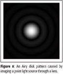
Figure 8
Lenses cannot image items smaller than their Airy disk; lenses that focus up to their Airy disk are called diffraction-limited. As such, it is important to know what the diffraction limit is of any lens. For a lens having a diameter d, the width w of the first dark circle of the Airy disk is

where λ is the wavelength of the light and f is the focal length of the lens. (The fraction f/d is called the f-number of the lens, which is a concept well-known to photographers.)
Diffraction limits demonstrate the inherent maximum ability of a lens to image an object. For example, if your lenses were made of sapphire (pure crystalline quartz), which has a cutoff wavelength of about 142 nm, a microscope having an f-number of 4 could only image an object of about 1.4 μm or larger. If you want to see something smaller, you are out of luck. The concept of diffraction limits demonstrates the characteristics that make better lenses: lower operating wavelengths (which depend upon the optical characteristics of the lens material), shorter focal lengths, and larger lens diameters (which bring their own problems: very large sizes of large lenses can distort the lens itself!).
David W. Ball is a professor of chemistry at Cleveland State University in Ohio. Many of his "Baseline" columns have been reprinted in book form by SPIE Press as The Basics of Spectroscopy, available through the SPIE Web Bookstore at www.spie.org. His most recent book, Field Guide to Spectroscopy (published in May 2006), is available from SPIE Press. He can be reached at d.ball@csuohio.edu; his website is academic.csuohio.edu/ball.
Optical Detection of Defects during Laser Metal Deposition: Simulations and Experiment
June 23rd 2022Igor Gornushkin and colleagues at BAM Federal Institute for Materials Research and Testing in Berlin, Germany studied the feasibility of using optical spectroscopy as a control method for laser metal deposition, and he recently spoke to us about this work. Gornushkin is the 2022 recipient of the Lester W. Strock Award from the New England Chapter of the Society for Applied Spectroscopy (SAS).

.png&w=3840&q=75)

.png&w=3840&q=75)


.png&w=3840&q=75)


.png&w=3840&q=75)


