Raman Crystallography and the Effect of Raman Polarizability Tensor Element Values
Raman spectroscopy is extremely useful for characterizing crystalline materials.
Group theory in conjunction with Raman polarization selection rules may be applied to the study and characterization of crystalline materials. The Polarization–Orientation (P-O) Raman method employs this relationship, and is useful for the identification of a material’s crystal class, orientation, degree of disorder, and determination of the symmetry species to which the Raman bands in a spectrum belong. Furthermore, it can be used to distinguish allotropes and polymorphs, differentiate single from polycrystalline materials, and determine whether materials at different locations in a fabricated device are crystallographically aligned. We discuss the theory and sensitivity of P-O Raman spectroscopy in the backscattering mode applied to crystals for which the nonzero Raman polarizability tensor elements of symmetry species are neither necessarily equal nor proportional. We demonstrate the effects of Raman polarizability tensor relative values and crystal orientation by calculating P-O Raman diagrams for the A and E symmetry species of the trigonal D3, C3v, and D3d crystal classes.
Raman crystallography is the application of group theory and Raman polarization selection rules to the study and characterization of crystalline materials. Characterizing crystalline materials by Raman spectroscopy is a good alternative when sample size or structure precludes one from doing so by X-ray diffraction. Where sample morphology or spatial variation of chemical composition or crystalline structure is on a scale that precludes or makes impractical the use of X-ray diffraction, polarized micro-Raman spectroscopy can often obtain crystallographic information. Applications of applied polarized Raman spectroscopy include characterization of minerals, integrated electronic and electro-optic devices, microelectromechanical systems (MEMS), and organic electronic devices including photovoltaics and organic light emitting diodes (OLEDs).
Most spectroscopists are familiar with Raman spectroscopy as a method of chemical analysis because of its sensitivity to the masses of a compound’s constituent atoms and their bond lengths and force constants. In addition, Raman spectroscopy can also be used for the characterization of the atomic structure of solids because Raman scattering depends on the polarization and direction of the incident light, the crystal symmetry and orientation of the solid sample, and the direction and polarization of the collected scattered light. Micro-Raman spectroscopic methods for determining local crystal orientation in silicon have been developed which take advantage of these properties (1,2). Raman crystallography can be applied to many materials, and the interested reader can find very elegant polarized Raman spectroscopic applications to characterize GaN (3), sapphire (4), and zirconia (5).
Polarization–Orientation Raman Spectroscopy
We discussed one method of Raman crystallography called Polarization–Orientation (P-O) Raman spectroscopy in a prior “Molecular Spectroscopy Workbench” installment (6). The P-O Raman method is useful for the identification of a material’s crystal class, orientation, degree of disorder, and determination of the symmetry species to which the Raman bands in a spectrum belong. To understand how this relationship can be applied to the characterization of crystals, we begin by considering the most fundamental expressions related to Raman scattering:
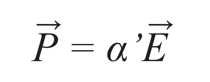
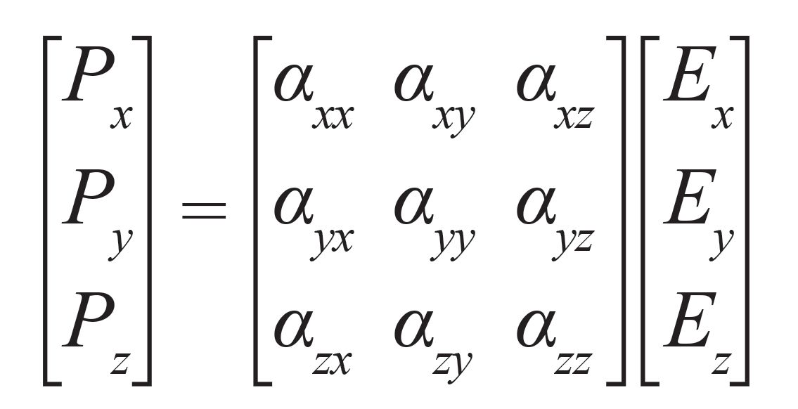
where α is the Raman polarizability tensor representing the vibrational modulation of the polarizability, E is the incident electric field vector, and P is the time varying dipole moment (also a vector) induced by the interaction of the incident electric field with the vibrationally modulated polarizability of the chemical bond. The Raman polarizability tensor is fixed relative to the positions of the atoms and the directions of the chemical bonds between them. Therefore, for a crystal fixed in space the relationship described by equations 1 and 2 is dependent upon the crystal symmetry and orientation of the sample relative to the direction and polarization of the incident and collected light. This relationship constitutes that part of the expression for Raman scattering intensity of interest to us in equation 3:

where IR is the Raman scattering intensity, IL is the intensity of the incident light, K is a factor incorporating the dependence on the frequency of the incident light, Ei, the polarization of the incident light, and Es and Ω are the polarization and solid angle, respectively, at which scattered light is collected. The significance of this expression for work with crystals is that Raman scattering intensity is proportional to the square of the dot product of the incident electric field vector, Raman polarizability tensor, and scattering vector.
The theory and general application of P-O Raman spectroscopy in the backscattering mode is based on the interdependence of incident electric field, Raman polarizability tensor and scattering vector. Most important is that the forms (whether elements are zero or nonzero) of the Raman polarizability tensors for crystals are dictated by the symmetry species of the crystal class to which the material belongs. The absolute magnitude of the tensor elements will be dictated by the specific chemical bonds between the atoms. However, whether a Raman tensor element is zero or nonzero is entirely dictated by the crystal symmetry. There are 32 crystal classes and the forms of the Raman polarizability tensors have been determined for all of them and tabulated in various publications (7–9).
In that previous introduction to P-O Raman spectroscopy, we demonstrated good agreement between the experimentally obtained results from single crystal Si and the calculated predictions for several crystallographic faces (6). The most common crystalline form of Si is cubic with two atoms in the primitive cell and belonging to crystal class Oh. The first order optical phonon at 520 cm-1 is triply degenerate and there are three T2g Raman polarizability tensors of the form:

where the letter d indicates a nonzero value. An experimental arrangement can be envisioned in which the laser beam is incident along the z-axis and polarized along the x-axis with respect to the laboratory reference frame. This arrangement corresponds to the Raman microscope backscattering configuration. A cubic single crystal Si chip is positioned such that its crystallographic XY-plane is coplanar with the laboratory XY-plane. Backscattered light is collected in two configurations, with the analyzer either parallel or perpendicular to the polarization of the incident laser light. Raman scattering strengths (normalized) equal to the square of the dot product in equation 3 have been calculated for the analyzer parallel and perpendicular to the incident polarization as the crystal is rotated in the XY-plane. The calculated P-O diagram for Raman backscattering signal strength of the first order optical phonon at 520 cm-1 from the XY-face of cubic Si is shown in Figure 1.
FIGURE 1: Calculated parallel (red) and perpendicular (blue) P-O Raman response from the XY-face of the Oh T2g mode, with all nonzero Raman polarizability tensor elements equal to 1. Excitation polarization is along the x-axis at a crystal angle of 0°.
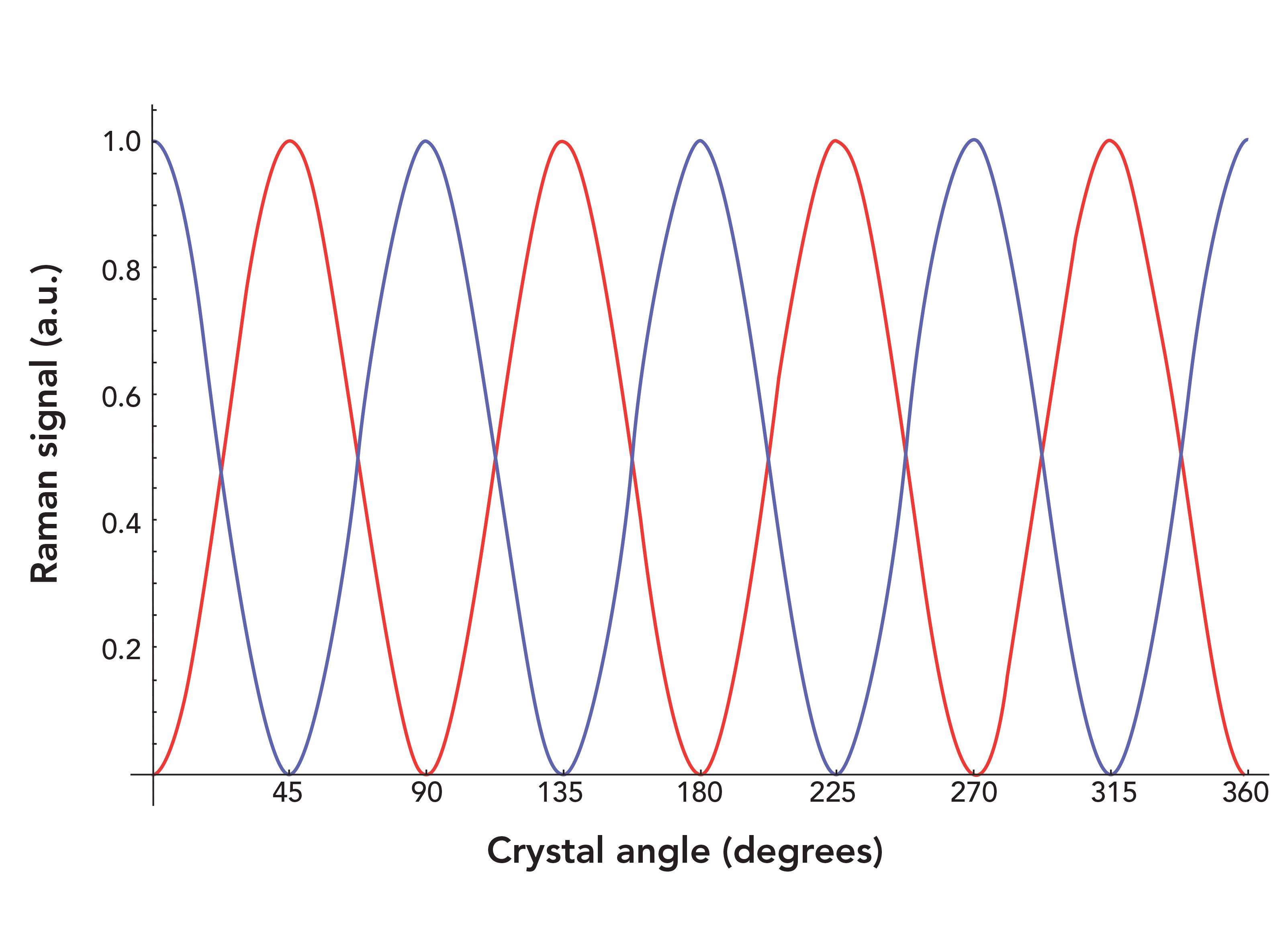
The parallel and perpendicular responses are sinusoidal functions 45° out of phase, and, of course, because of the cubic symmetry the response is the same for the XZ- and YZ-faces. However, if the crystal is oriented out of these planes, one begins to see the effect of orientation on the P-O Raman plots. The method used to transform the Raman polarizability tensors from one crystal orientation to another is the transformation through Euler’s angles (10). The interested reader can refer to our previous publication to compare the P-O Raman results for the (100), (110) and (111) faces of cubic Si (6).
We have performed P-O Raman calculations for many other Si crystal orientations and have found the method to be very sensitive to crystal orientation. In fact, this sensitivity will be true for crystals of all symmetry classes because the P-O Raman diagrams depend only on the forms of the Raman polarizability tensors. Crystals of symmetry lower than that of the cubic system can have Raman polarizability tensors in which the nonzero elements are not equal, and in those cases, the P-O diagram will be affected by the relative magnitudes of the tensor elements. In fact, comparing calculated P-O Raman diagrams to the experimentally obtained P-O plots allows one to infer relative Raman scattering cross-sections of vibrational modes from crystals. The form or pattern of P-O Raman diagrams are dependent upon crystal symmetry and the relative magnitudes of the nonzero tensor elements, which depend upon the specific elemental, compositional, or molecular identity of the crystal. That is what makes the P-O Raman method a useful basis for Raman crystallography.
One can immediately recognize the application of this method for the characterization of crystal structure and orientation in either naturally occurring materials or fabricated devices. The P-O Raman method is complementary to X-ray diffraction, and should be considered when X-ray analysis is not practical or possible. P-O Raman spectroscopy may be used to identify vibrational modes, distinguish allotropes and polymorphs, distinguish single from polycrystalline materials, and determine orientation of the crystal and degree of disorder. Furthermore, one can determine whether materials at different locations in a fabricated device are crystallographically aligned based upon the phases of the experimentally obtained P-O Raman diagrams.
P-O Raman Spectroscopy of the D3, C3v, and D3d Crystal Classes
The nonzero elements of the triply degenerate T2g Raman polarizability tensors of the Oh crystal class are all equal. Therefore, only the crystal orientation can affect the P-O Raman diagram for that symmetry species. The cubic system is a special case of high symmetry and all of the nonzero tensor elements of the various symmetry species of the cubic classes are either equal or proportional to each other. That is not the case for the other 27 crystal classes that do not belong to the cubic system.
Here, we discuss the theory and more general application of P-O Raman spectroscopy in the backscattering mode applied to crystals for which the nonzero Raman tensor elements of symmetry species are neither equal nor proportional. We demonstrate the effects of Raman tensor relative values and crystal orientation by calculating P-O Raman diagrams for the A and E symmetry species of the trigonal D3, C3v, and D3d crystal classes. The Raman tensors of these symmetry species are shown in equation 5. The E symmetry species is doubly degenerate and so there are two Raman polarizability matrices associated with that species.

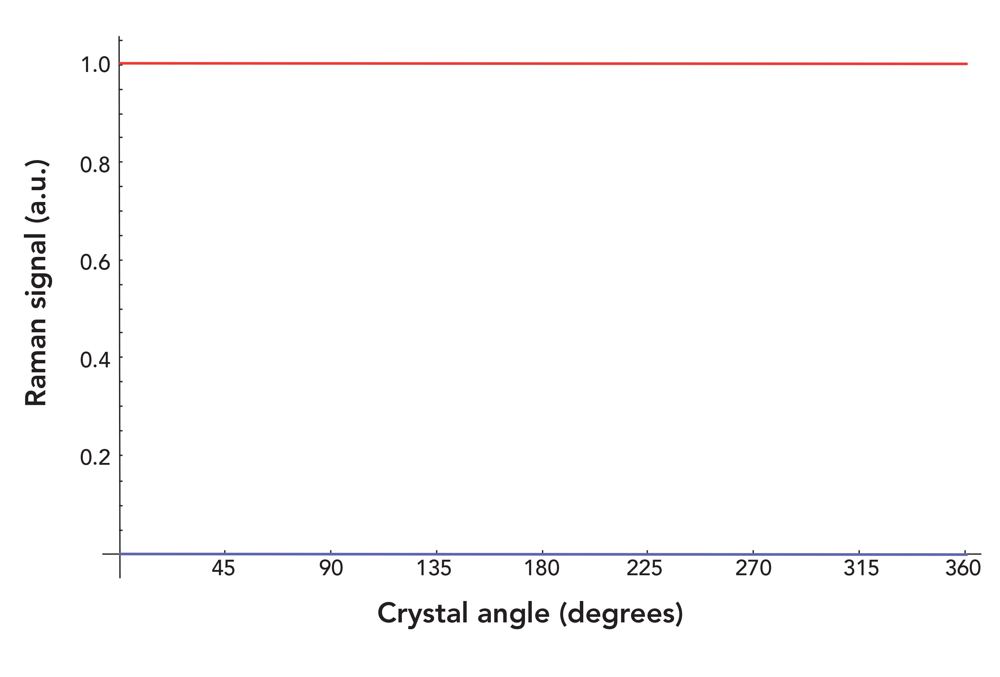
We begin our discussion with the A symmetry species in equation 5 and note that only the diagonal tensor elements are nonzero. Furthermore, αxx= αyy ≠ αzz, and, as we will see, the relative magnitudes of the tensor elements will affect the PO Raman diagram depending upon the sample’s crystal orientation. The P-O Raman experimental arrangement can be envisioned in which the laser beam is directed along the z-axis and polarized along the x-axis, with respect to the sample’s crystallographic axes and at a crystal rotational angle of 0°. The XY-face of the trigonal D3, C3v, or D3d crystal is positioned coplanar with the XY-plane of the laboratory frame, and backscattered light is collected along the z-axis. Raman scattering strengths for αxx = αyy = 1 and αzz = 10 have been calculated for the analyzer parallel and perpendicular to the incident polarization as the crystal is rotated in the XY-plane. The calculated P-O diagram for Raman backscattering signal strength from the XY-face of the A symmetry species of a trigonal D3, C3v, or D3d crystal is shown in Figure 2. The P-O Raman responses for both parallel and perpendicular configurations are invariant with crystal orientation. The parallel Raman signal is allowed and always equal to the squared αxx and αyy values of 1, whereas the perpendicular response is forbidden, yielding a Raman signal of zero. Mathematically, the reason for these responses is that both diagonal tensor elements within the XY-plane of rotation are equal to 1, whereas αzz is perpendicular to the plane of rotation, and does not contribute to the signal in the backscattering configuration. In this experimental arrangement the specific value of αzz, which in this example is 10, has no effect on the P-O Raman diagram.
FIGURE 2: Calculated parallel (red) and perpendicular (blue) P-O Raman response from the XY-face of the trigonal D3, C3v, or D3d A1 mode, with αxx,yy = 1 and αzz = 10. Excitation polarization is along the x-axis at a crystal angle of 0°. The parallel and perpendicular responses are invariant with crystal angle, and have Raman signals of 1 and 0, respectively.
Now, envision rotating the crystal 90° such that the laser is incident upon the YZ-face and is polarized along the z-axis when the crystal rotation angle is at 0°. Relative Raman scattering strengths have been calculated for the analyzer parallel and perpendicular to the incident polarization as the crystal is rotated in the YZ-plane. In this configuration, the relative magnitudes of the αyy and αzz values directly affect the P-O Raman diagram, because the crystal rotation is in the YZ-plane and the dot product of equation 3 varies with crystal orientation. The calculated P-O diagrams for Raman backscattering signal strength from the YZ-face of the A symmetry species of a trigonal D3, C3v, or D3d crystal for αxx = αyy = 1 and various αzz values are shown in Figure 3. Note that the P-O Raman diagrams of the YZ- and XZ-faces are identical because the αxx and αyy values are equal.
FIGURE 3: Calculated parallel (red) and perpendicular (blue) P-O Raman re- sponse from the YZ-face of the trigonal D3, C3v, or D3d A1 mode, with αxx,yy = 1 and αzz = (a) 0.01, (b) 0.25, (c) 0.5, (d) 0.75. Excitation polarization is along the z-axis at a crystal angle of 0°.
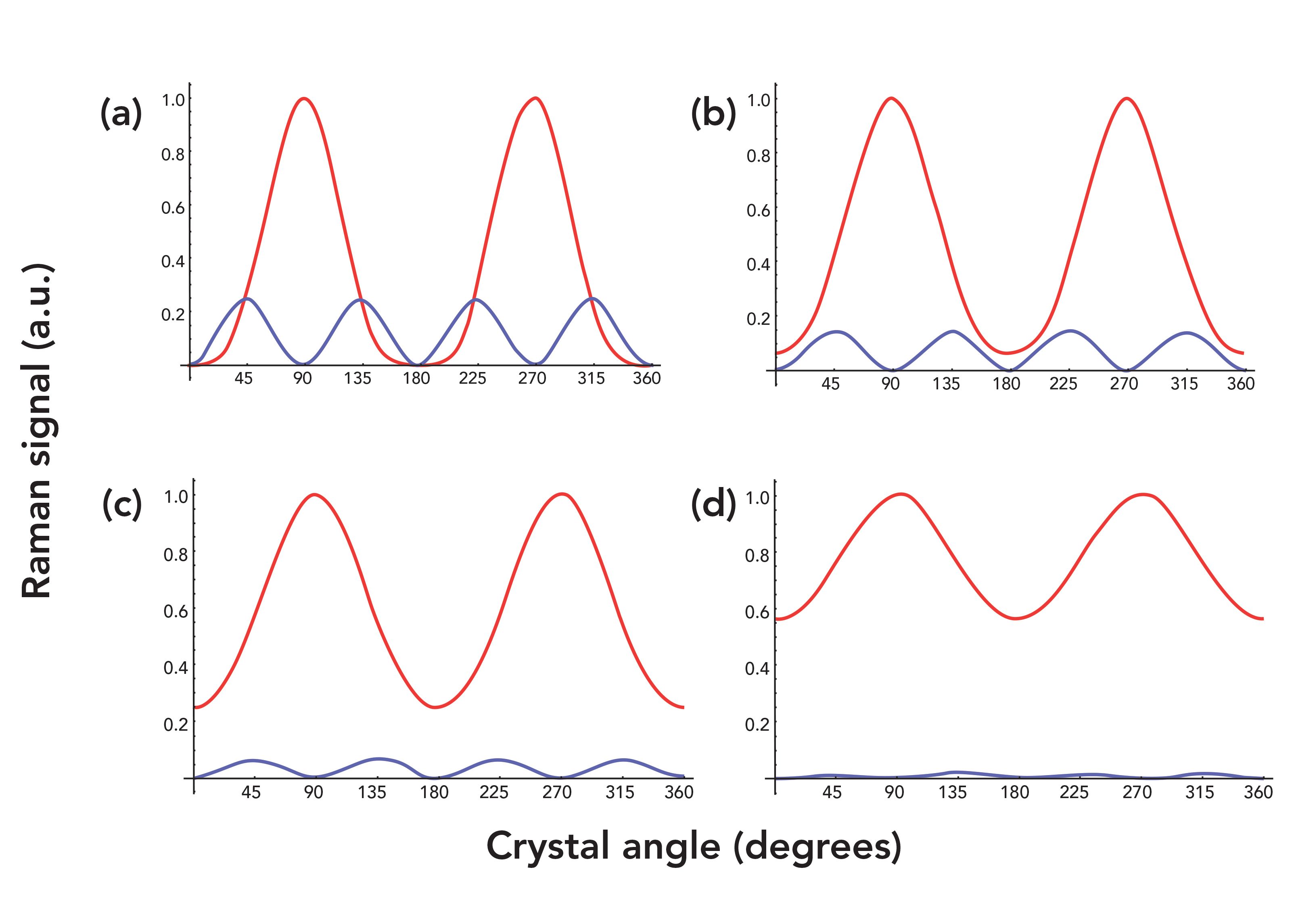
The αzz values for the P-O Raman diagrams in Figure 3 are 0.01, 0.25, 0.5, and 0.75, all less than 1, the value we designated for αxx and αyy. The Raman signal strengths for parallel and perpendicular configurations vary with crystal orientation, with the perpendicular response varying at twice the frequency as that of the parallel configuration. The P-O Raman diagrams of the A symmetry species obtained from the YZ-face are entirely different from that of the XY-plane, which was invariant with crystal angle. That is because the contributing Raman tensor elements are not equal when probing the YZ-face, whereas those contributing in the XY-plane are equal. The Raman signal reaches a maximum in the parallel configuration at 90° and 270°, whereas in the perpendicular configuration the Raman signal peaks at 45°, 135°, 225°, and 315°. The crystal angle separation between the maxima are 180° and 90° for the parallel and perpendicular polarization configurations, respectively. The P-O Raman response maxima remain at the same angles of crystal orientation for all αzz values less than that of αyy. However, there are two noticeable variations in the P-O Raman diagrams, as the αzz values are changed relative to that of αyy. The valley at 180° becomes less broad and more rounded with increasing αzz values. Also, the amplitudes of the parallel and perpendicular responses decrease, and the two functions separate, as the αzz values approach that of αyy. These calculated P-O Raman diagrams demonstrate that experimentally obtained P-O Raman responses can be used to identify the crystalline face, assign the symmetry species of a particular Raman band, and determine the relative values of the αxx, αyy, and αzz Raman polarizability tensor elements of the A symmetry species when αxx = αyy > αzz.
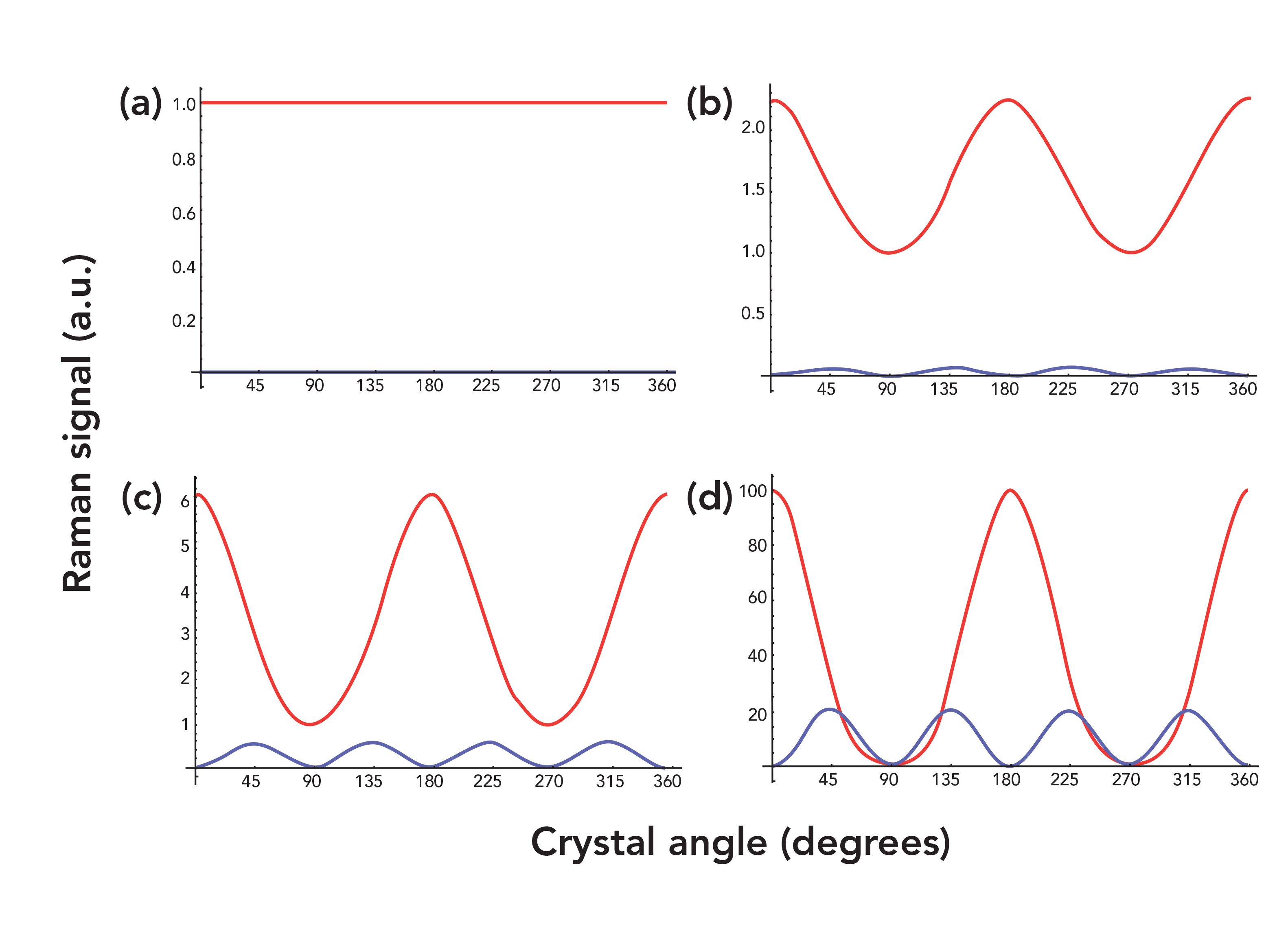
Now, we examine those cases in which the Raman tensor values of the A symmetry species are αxx = αyy ≤ αzz. The αzz values for the P-O Raman diagrams in Figure 4 are 1, 1.5, 2.5, and 10, all greater than or equal to the value we designated for αyy. The P-O Raman responses for both parallel and perpendicular configurations are invariant with crystal orientation when αxx = αyy = αzz = 1. The parallel Raman signal is allowed, and always equal to the squared αyy and αzz values of 1, whereas the perpendicular response is forbidden yielding a Raman signal of zero. This is the response that one would expect because, mathematically, the situation here is the same as for the XY-face P-O Raman diagram shown in Figure 2, where the contributing diagonal Raman tensor elements are equal. Looking back at Figure 3 with Figure 4a in mind, one can see the progression of the P-O Raman diagrams culminating in the invariant response of Figure 4a as the value of αzz approaches that of αyy. The P-O Raman diagram of Figure 4b, with αzz = 1.5, appears similar to that of Figure 3d, with αzz = 0.75, with respect to the separation of the parallel and perpendicular responses. However, the phases of the parallel responses in Figures 4b–d are shifted 90° relative to those in Figure 3. Now the Raman signal reaches a maximum in the parallel configuration at 0°, 180°, and 360°, whereas in the perpendicular configuration the Raman signal peaks at 45°, 135°, 225°, and 315°, just as it did for αyy > αzz. The phase shift of the A symmetry species P-O Raman parallel response informs us whether the αzz value is greater or less than that of αyy, and the amplitudes and separations of the parallel and perpendicular responses allow us to determine the relative magnitudes of the contributing Raman polarizability tensor elements.
FIGURE 4: Calculated parallel (red) and perpendicular (blue) P-O Raman response from the YZ-face of the trigonal D3, C3v, or D3d A1 mode, with αxx,yy = 1 and αzz = (a) 1, (b) 1.5, (c) 2.5, (d) 10. Excitation polarization is along the z-axis at a crystal angle of 0°. The parallel and perpendicular responses of 4(a) are invariant with crystal angle and have Raman signals of 1 and 0, respectively.
Thus far, we have discussed the P-O Raman response of only the A symmetry species. Now we turn our attention to the Raman active doubly degenerate E symmetry vibrational modes. The two E Raman polarizability tensors shown in equation 5 both apply when calculating the P-O Raman diagram for this symmetry species because of its double degeneracy. You can see from equation 5 that the E symmetry species is more complicated, because it has both diagonal and off-diagonal Raman tensor elements that are nonzero. Also, there are both positive and negative tensor element values. Nevertheless, there are only two absolute values or magnitudes in the two Raman tensors indicated by the letters c and d in equation 5. The differences of the magnitudes of tensor elements c and d can yield a wide variety of P-O Raman diagrams. We show just a sampling here so that you can get a sense of how sensitive the P-O Raman method is to crystal orientation and the relative values of the Raman tensor elements.
The P-O Raman experimental arrangement can be envisioned in which the laser beam is directed along the z-axis and polarized along the x-axis with respect to the sample’s crystallographic axes and at a crystal rotational angle of 0°. The XY-face of the trigonal D3, C3v, or D3d crystal is positioned coplanar with the XY-plane of the laboratory frame, and backscattered light is collected along the z-axis. Raman scattering strengths for αxx = 2, αyy,xy,yx = -2,αyz,zy = 1, and αxz,zx = -1 have been calculated for the analyzer parallel and perpendicular to the incident polarization as the crystal is rotated in the XY-plane. The calculated P-O diagram for Raman backscattering signal strength from the XY-face of the E symmetry species of a trigonal D3, C3v, or D3d crystal is shown in Figure 5. The P-O Raman responses for both parallel and perpendicular configurations are invariant with crystal orientation and each is equal to a Raman signal of 4, the square of the tensor values αxx = 2 and αyy,xy,yx = -2. Mathematically, the reason for these responses is that only the Raman tensor elements within the XY-plane of rotation contribute to the Raman signal, and they all have the same absolute value of 2. The nonzero Raman tensor elements αyz,zy and αxz,zx are perpendicular to the plane of rotation, and do not contribute to the signal in the backscattering configuration. In this experimental arrangement the specific value of αyz,zy and αxz,zx, which in this example is 1, has no effect on the P-O Raman diagram.
FIGURE 5: Calculated parallel (red) and perpendicular (blue) P-O Raman response from the XY-face of the trigonal D3, C3v, or D3d E mode, with αxx = 2, αyy,xy,yx = -2, αyz,zy = 1, and αxz,zx = -1. Excitation polarization is along the x-axis at a crystal angle of 0°. The parallel and perpendicular responses are invariant with crystal angle, and both equal a Raman signal of 4.
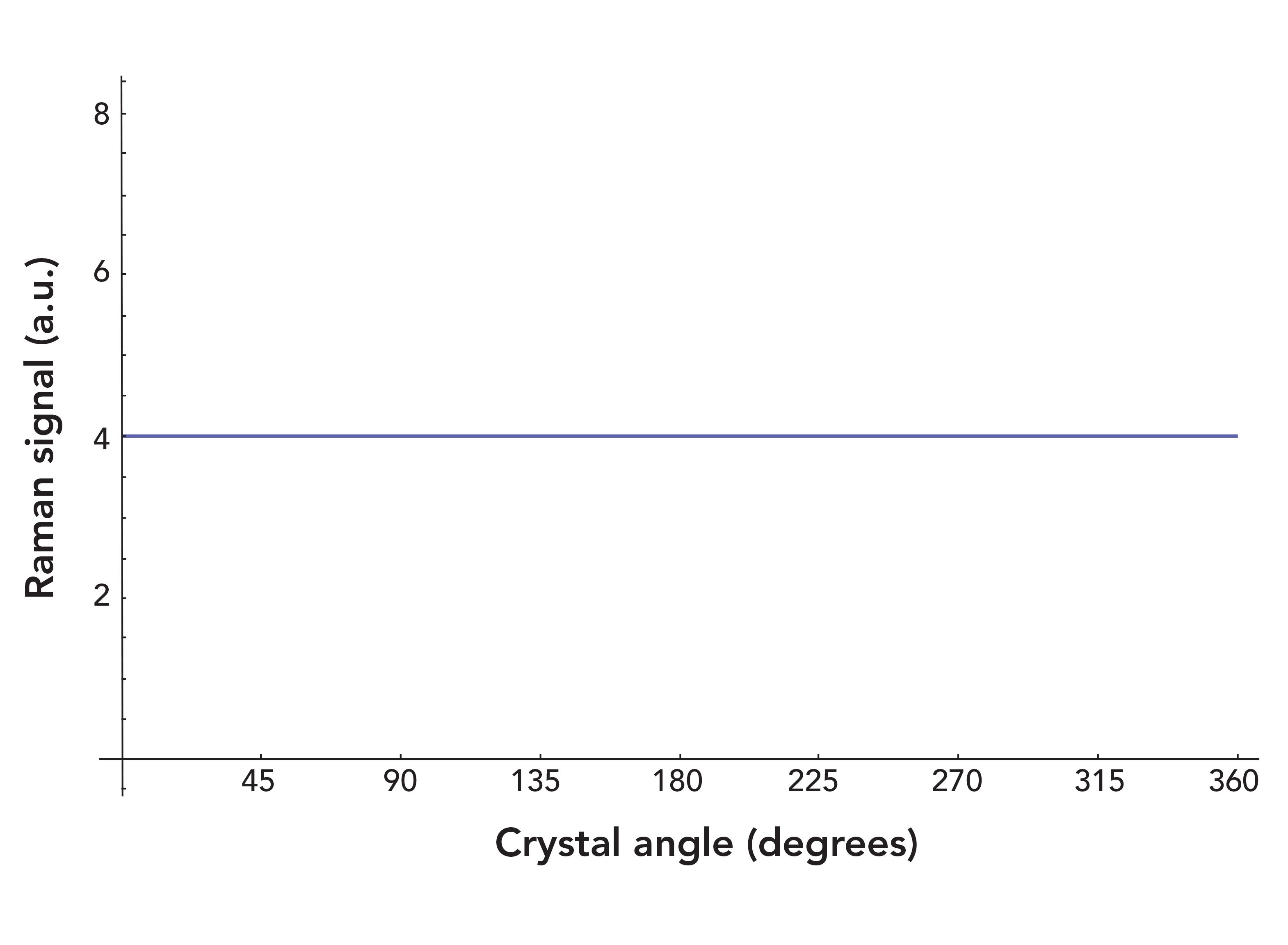
Note that the P-O Raman diagrams of both the A and E symmetry species are invariant with crystal orientation within the XY-plane. Nevertheless, the two symmetry species can be differentiated and assigned to Raman bands from P-O Raman plots experimentally obtained from the XY-face of a crystal belonging to a trigonal D3, C3v, or D3d crystal class. That is because the perpendicular response of the A symmetry species is not allowed, whereas that of the E symmetry species is allowed and is equal to the parallel configuration response.
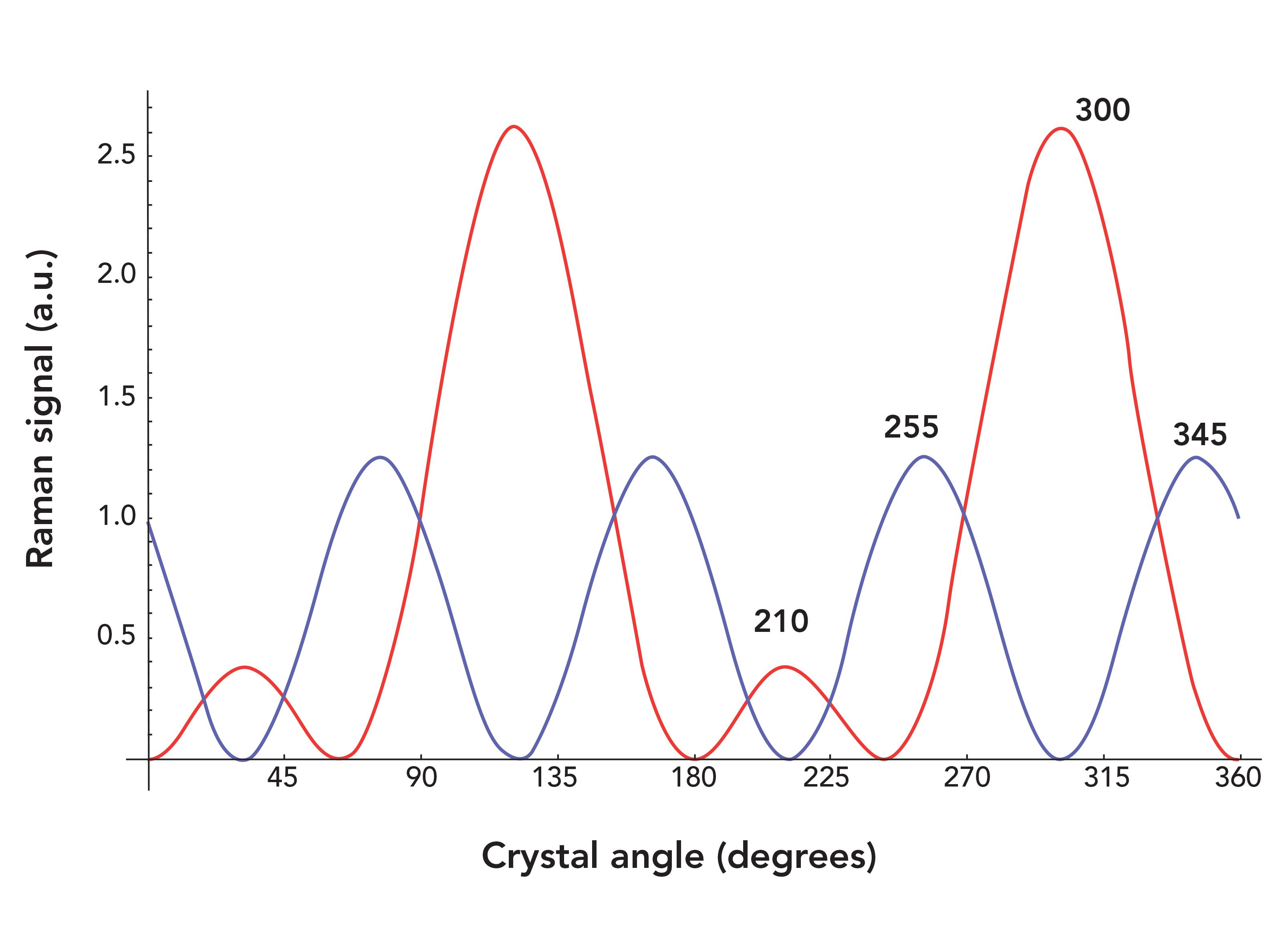
Now, envision rotating the crystal 90° such that the laser is incident upon the YZ-face and is polarized along the z-axis when the crystal rotation angle is at 0°. Relative Raman scattering strengths have been calculated for the analyzer parallel and perpendicular to the incident polarization as the crystal is rotated in the YZ-plane. Figure 6 shows the P-O Raman diagram for the YZ-face of a trigonal D3, C3v, or D3d E mode with αxx = 1, αyy,xy,yx y = -1, αyz,zy = 1, and αxz,zx = -1. Here, the P-O Raman diagram is no longer invariant with crystal orientation, even though the nonzero tensor absolute values contributing to the YZ-plane are all equal to 1. The P-O Raman diagram is oscillatory, and the parallel and perpendicular responses differ from each other in phase by 45°. The last two maxima of the parallel and perpendicular responses are labeled, and you can see that their separation within each configuration is 90°. Of course, the c and d nonzero tensor elements of equation 5 are not likely to be equal for a real uniaxial crystal. However, setting them equal demonstrates that the oscillatory response of the P-O diagram as shown in Figure 6 arises primarily from the contribution of the nonzero off-diagonal tensor elements to the YZ-plane, whereas equal values assigned to the diagonal and off-diagonal tensor elements within the XY-plane as in Figure 5 generate a P-O Raman diagram invariant with crystal rotation.
FIGURE 6: Calculated parallel (red) and perpendicular (blue) P-O Raman response from the YZ-face of the trigonal D3, C3v, or D3d E mode, with αxx = 1, αyy,xy,yx = -1, αyz,zy = 1, and αxz,zx = -1. Excitation polarization is along the z-axis at a crystal angle of 0°.
Having reviewed the P-O Raman response when the absolute values of the nonzero Raman tensor elements are equal, now let us analyze the effects when the relative magnitudes of the c and d nonzero tensor elements of equation 5 are varied. Figure 7a shows the P-O Raman diagram generated when αxx = 1.5, αyy,xy,yx = -1.5, αyz,zy = 1, and αxz,zx = -1; the absolute value of the Raman tensors in the XY-plane equals 1.5, and that in the XZ- and YZ-planes equals 1. We can see the effect of the increase in tensor magnitudes in the XY-plane by comparing this P-O Raman diagram with that of Figure 6. There are two noticeable differences between the two. The first is that the parallel and perpendicular responses in Figure 7a are shifted -5° relative to those in Figure 6 (the last two maxima of the parallel and perpendicular responses are labeled to assist in recognizing this shift). Also, the first and third maxima of the parallel configuration in Figure 7a peak at a lower signal strength than that of the corresponding maxima in Figure 6. Increasing the absolute value of the Raman tensors in the XY-plane to αxx = 5, αyy,xy,yx = -5, αyz,zy = 1, and αxz,zx = -1 advances this progression, as shown in Figure 7c. Both parallel and perpendicular responses are shifted -15° relative to those in Figure 7a. Also, the first and third maxima of the parallel configurations in Figures 6 and 7a have now vanished.
FIGURE 7: Calculated parallel (red) and perpendicular (blue) P-O Raman response from the YZ-face of the trigonal D3, C3v, or D3d E mode, with (a) αxx = 1.5, αyy,xy,yx = -1.5, αyz,zy = 1, and αxz,zx = -1; (b) αxx = 1, αyy,xy,yx = -1, αyz,zy = 1.5, and αxz,zx = -1.5; (c) αxx = 5, αyy,xy,yx = -5, αyz,zy = 1, and αxz,zx = -1; (d) αxx = 1, αyy,xy,yx = -1, αyz,zy = 5, and αxz,zx = -5. Excitation polarization is along the z-axis at a crystal angle of 0°.
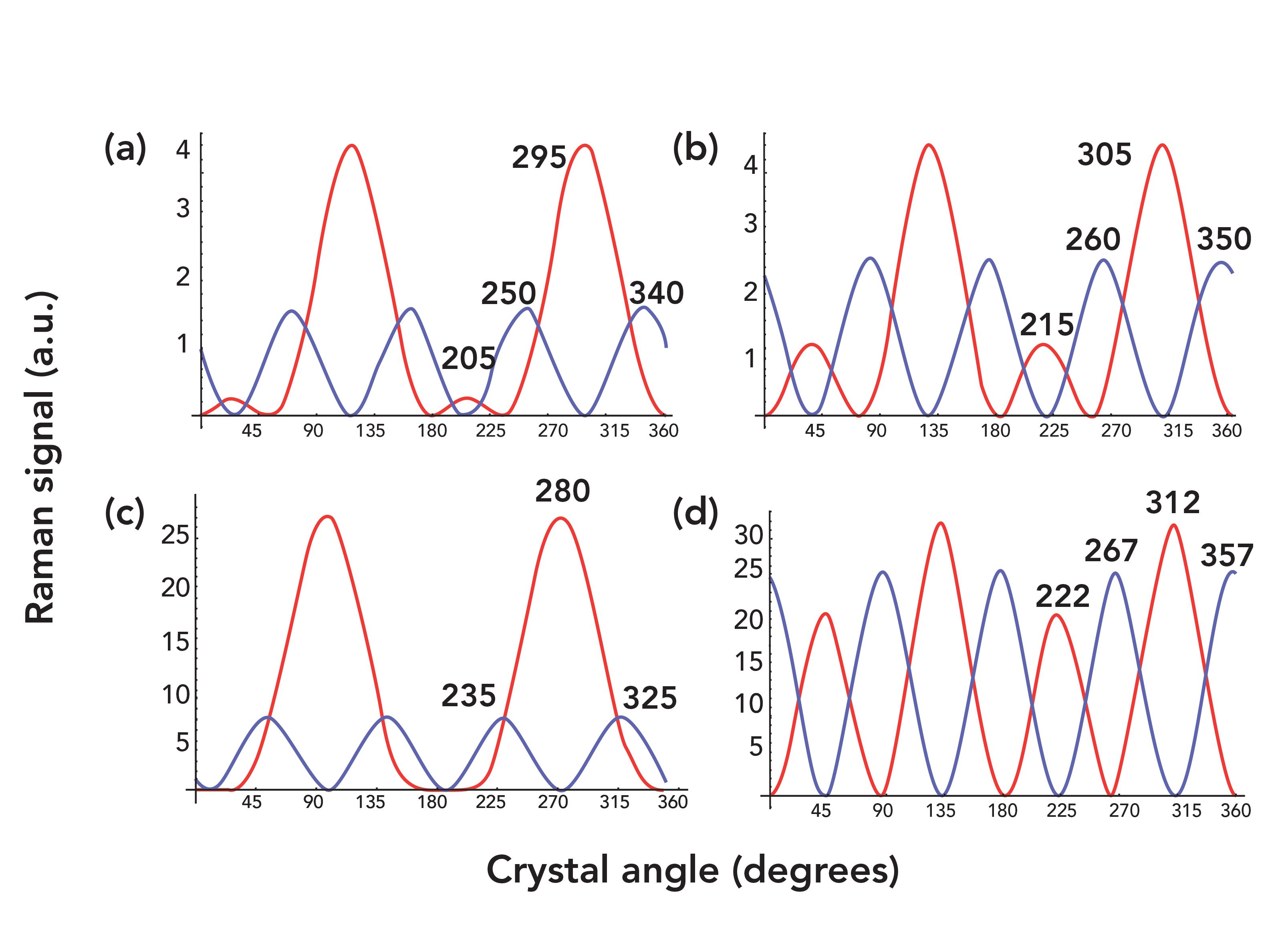
It is useful to reverse the Raman tensor magnitudes of the XY-plane and the XZ- and YZ-planes, as shown in Figures 7b and 7d, to see the effects on the P-O Raman diagram. Compare the P-O Raman diagrams of Figures 7a and 7b in which the magnitudes of the Raman tensor elements have been maintained but simply reversed for the planes containing the ordinary axes (x and y) and the extraordinary axis (z). The parallel and perpendicular responses in Figure 7b appear similar to those in Figure 7a but are not identical. Several differences are clear. First, the phases of both the parallel and perpendicular responses of Figure 7b are shifted +10° relative to those in Figure 7a. Additionally, the first and third maxima of the parallel configurations in Figure 7b are more intense than the corresponding maxima in Figure 7a. Finally, the perpendicular response in Figure 7b is relatively stronger than that in Figure 7a. We see a similar progression when comparing the P-O Raman diagrams of Figures 7c and 7d. The phases of both the parallel and perpendicular responses of Figure 7d are shifted +32° relative to those in Figure 7c. Also, the perpendicular response in Figure 7d is relatively stronger than that in Figure 7c.
These subtle effects of the Raman tensor magnitudes on the phases and amplitudes of the P-O Raman diagrams are not intuitive. One might expect that such changes would occur if a crystal is rotated to some degree off of its crystallographic axis with respect to the direction of laser propagation, but not from changes in the Raman tensor magnitudes. P-O Raman calculations help one to anticipate and understand these effects. This observation is important, because more Raman spectroscopists are using experimental methods of laser polarization in conjunction with sample orientation to infer crystal phase and orientation along with the assignment of symmetry species to particular Raman bands. The calculated P-O Raman diagrams show how significantly the magnitudes of the Raman tensor elements affect the P-O Raman results and make clear that such calculations are necessary to properly interpret the experimentally obtained results of polarized Raman measurements obtained from crystals whose Raman tensor elements are not equal.
Conclusion
In this article, we discussed the application of group theory and Raman polarization selection rules to the study and characterization of crystalline materials. Specifically, we described one method of Raman crystallography called polarization–orientation Raman spectroscopy. The P-O Raman method has been shown to be useful for the identification of a material’s crystal class, orientation, degree of disorder, and determination of the symmetry species to which the Raman bands in a spectrum belong. Here, we discussed the theory and more general application of P-O Raman spectroscopy in the backscattering mode applied to crystals for which the nonzero Raman polarizability tensor elements of symmetry species are neither necessarily equal nor proportional. We demonstrated the effects of Raman polarizability tensor relative values and crystal orientation by calculating P-O Raman diagrams for the A and E symmetry species of the trigonal D3, C3v, and D3d crystal classes. The calculated P-O Raman diagrams show how significantly the magnitudes of the Raman polarizability tensor elements affect the P-O Raman results, and make clear that such calculations are necessary to properly interpret and understand the experimentally obtained results of polarized Raman measurements obtained from crystals whose Raman polarizability tensor elements are not equal.
References
(1) J.B. Hopkins and L.A. Farrow, J. Appl. Phys. 59, 1103–1110 (1986).
(2) K. Mizoguchi and S. Nakashima, J. Appl. Phys. 65, 2583–2590 (1989).
(3) H.C. Lin, Z.C. Feng, M.S. Chen, Z.X. Shen, I.T. Ferguson, and W. Lu, J. Appl. Phys. 105, 036102 (2009).
(4) M.C. Munisso, W. Zhu, and G. Pezzotti, Phys. Status Solidi B 246(8), 1893–1900 (2009).
(5) K. Fukatsu, W. Zhu, and G. Pezzotti, Phys. Status Solidi B 247(2), 278-287 (2010).
(6) D. Tuschel, Spectroscopy 27(3), 22–27 (2012).
(7) R. Loudon, Adv. Phys. 13, 423–482 (1964); Erratum: R. Loudon, Adv. Phys. 14, 621–621 (1965).
(8) G. Turrell, Infrared and Raman Spectra of Crystals (Academic Press, New York, New York, 1972), pp. 358–361.
(9) G. Turrell, in Practical Raman Spectroscopy, D.J. Gardiner and P.R. Graves, Eds. (Springer-Verlag, New York, New York, 1989), pp. 22–24.
(10) E.B. Wilson, Jr., J.C. Decius, and P.C. Cross, Molecular Vibrations: The Theory of Infrared and Raman Vibrational Spectra (McGraw-Hill, New York, New York, 1955), p. 285.

David Tuschel is a Raman applications scientist at Horiba Scientific, in Piscataway, New Jersey, where he works with Fran Adar. David is sharing authorship of this column with Fran. He can be reached at: SpectroscopyEdit@MMHGroup.com.

AI-Powered SERS Spectroscopy Breakthrough Boosts Safety of Medicinal Food Products
April 16th 2025A new deep learning-enhanced spectroscopic platform—SERSome—developed by researchers in China and Finland, identifies medicinal and edible homologs (MEHs) with 98% accuracy. This innovation could revolutionize safety and quality control in the growing MEH market.
New Raman Spectroscopy Method Enhances Real-Time Monitoring Across Fermentation Processes
April 15th 2025Researchers at Delft University of Technology have developed a novel method using single compound spectra to enhance the transferability and accuracy of Raman spectroscopy models for real-time fermentation monitoring.
Nanometer-Scale Studies Using Tip Enhanced Raman Spectroscopy
February 8th 2013Volker Deckert, the winner of the 2013 Charles Mann Award, is advancing the use of tip enhanced Raman spectroscopy (TERS) to push the lateral resolution of vibrational spectroscopy well below the Abbe limit, to achieve single-molecule sensitivity. Because the tip can be moved with sub-nanometer precision, structural information with unmatched spatial resolution can be achieved without the need of specific labels.