Raman Spectroscopy of Oil Shale
Characterizing oil shale, particularly black shale consisting of kerogen, with Raman spectroscopy


Here, we discuss the use of Raman spectroscopy to characterize oil shale, particularly black shale, which consists of kerogen (fossilized organic matter) trapped in sedimentary rock consisting of clays, calcites, silicates, and titanium dioxides among other inorganic minerals. We show that Raman spectroscopy is useful for characterizing the varieties of kerogen structure (chemical bonding and solid state), differentiating shales with different relative amounts of kerogen to inorganic mineral, and differentiating polymorphs of naturally occurring inorganic oxides.
Although there has been a lot of attention given recently to oil shale, its discovery occurred many decades ago. In researching this topic, I found a 1923 report in Chemical & Engineering News about the work of Ralph H. McKee of Columbia University, who advanced what were at that time "new arguments for the shale oil recovery process" at a meeting of the American Chemical Society and the Providence Engineering Society (1). Quite remarkably, the title of McKee's presentation was "Future Sources of Gasoline." He reported on his petrochemical studies of heating oil shale to produce kerosene, gasoline, and various lubricating oils. More than 30 years later, one can read that "Northwestern Colorado's oil shale deposits probably contain the greatest concentration of undeveloped energy to be found any place in the world. So says Union Oil of California's president A.C. Rubel," from a 1957 issue of Chemical & Engineering News (2). The potential of and interest in oil shale as a source for fuel and other petrochemical products continues to this day and attracts many to the Oil Shale Symposium held annually at the Colorado School of Mines in Golden, Colorado. In fact, I attended the 32nd Annual Oil Shale Symposium in October 2012 and found it to be a very well organized, informative, and beneficial conference with an opportunity to participate in a two-day field trip to the Green River Formation in northwestern Colorado and southern Utah following the conference. I encourage readers who are interested in this subject and attending the 2013 Oil Shale Symposium to consult the Colorado School of Mines web site.
Let's begin with a clarification of the nomenclature used in this field. The term oil shale refers to the sedimentary rock from which oil is recovered through a high-temperature chemical (industrial retort) process. The oil shale is porous rock in which organic matter called kerogen is trapped. As Jehlicka and colleagues stated, "Kerogen is defined as dispersed organic matter from sedimentary and metasedimentary rocks or as the insoluble part of the organic matter of rocks. The insolubility means here the insolubility in water, organic solvents, hydroxides and mineral acids (strong oxygen containing acids excluded)" (3). I very much like the analogy that Professor Jeremy Boak of the Colorado School of Mines uses when he compares the words oil shale to wine grapes. Of course, there is no wine in the grapes, but wine can be generated from the grapes through chemical processes and fermentation, hence the distinction between oil shale and oil from shale. Understanding and optimizing the chemical processes for producing fuel oil and other petrochemical products from sedimentary shale permeated with kerogen (oil shale) remains a fertile area of chemical research.
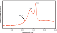
Figure 1: Raman spectrum of black shale. The Raman bands at 1354 and 1603 cm-1are attributable to kerogen.
Black Shale Consisting of Kerogen and Calcite
Kerogen is defined as fossilized organic matter and as such consists mostly of carbon. Not surprisingly then, the spectrum of kerogen very much resembles that of amorphous elemental carbon. A typical Raman spectrum of black shale shown in Figure 1 consists primarily of kerogen and calcite (calcium carbonate). The broad band centered at approximately 1354 cm-1 is commonly referred to as the "D band," where the letter D stands for disorder. The sharper and narrower band at 1603 cm-1 is designated the "G band," where the letter G stands for graphite. As in the case for the various forms of amorphous carbon (4), there is not a unique spectrum of kerogen (3). In fact, Kelemen and Fang (5) have studied coals and kerogens from a variety of sources and published their work relating the bandwidths, band separations, and relative integrated intensities of the D and G bands of Green River and Bakken kerogens to vitrinite reflectance measurements, which are often used as a measure of organic metamorphism. Their work is a fine example of the efforts to establish a correlation between Raman spectral characteristics and the maturation or diagenesis of kerogen. Through Raman spectroscopy they have correlated the changes in chemical bonding and solid state structure to the degree of maturation or extent of catagenesis and metagenesis that has occurred in the natural state of the organic material. Interested readers should consult Kelemen and Fang's publication from Energy & Fuels for more detail.
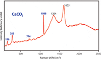
Figure 2: Raman spectrum of black shale with considerably more calcium carbonate relative to kerogen than that observed in Figure 1.
Oil shale, and a subset of that material categorized as black shale, consists of kerogen trapped in the pores of sedimentary rock consisting primarily of silicates and calcite. The presence of calcite, which is detected in the Raman spectrum of Figure 1, is more evident in the Raman spectrum of Figure 2. Here we see the kerogen bands along with the much sharper bands at 156, 282, 714, and 1088 cm-1 that reveal the presence of crystalline calcium carbonate or calcite. In this instance, we presume that there is less kerogen and relatively more calcite in the focal volume of the laser beam than in the sample from Figure 1. Consequently, the signal-to-noise ratio of the kerogen scattering is lower and the calcite, occupying relatively more of the sample volume, contributes more Raman scattering to the spectrum. In fact, in principle one can use the relative intensities of the calcite and kerogen bands as a proxy for the relative amount of kerogen to calcite from sample-to-sample or even within a sample for various locations. Raman spectra obtained from black shale at different locations are shown in Figure 3. These spectra clearly demonstrate the dramatic variability of the relative calcite-to-kerogen Raman strengths that can be observed in black shale. By generating reference samples of known amounts of kerogen and calcite, one could use the relative Raman strengths to perform quantitative analysis of the black shale. Of course, doing so is not as trivial as it sounds and caution must be exercised in quantitatively interpreting the data. As we mentioned earlier, and as you'll see in the next section, there is no unique Raman spectrum of kerogen. Therefore, although in principle a quantitative determination of the relative amounts of calcite and kerogen could be performed, an accurate and precise assay would require that the chemical bonding and solid-state structure of the kerogen reference would have to match that of the sample being analyzed. A proper qualitative analysis of the kerogen spectra is a necessary precondition for any attempt to use Raman spectroscopy for quantitative analysis of oil shale.
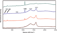
Figure 3: Raman spectra from different areas of black shale indicating the varying amounts of calcium carbonate relative to kerogen.
The Varieties of Kerogen Raman Spectra
Calcite is not the only mineral to be found in either oil shale rock or black shale. The Raman spectrum in Figure 4 consists of contributions from kerogen and the anatase form of titanium dioxide, TiO2(6). However, let's first focus on the kerogen contribution to the spectrum; we will discuss the TiO2component in the next section. It is in black shale samples with TiO2that we begin to see the differences in the Raman spectra of kerogen that relate to its chemical bonding and solid-state structure. Note the clear differences between the kerogen component of Figure 4 compared to those observed in the individual spectra of Figures 1 and 2. The D and G bands in Figure 4 are at 1360 and 1592 cm-1, whereas those in Figures 1 and 2 are at 1354 and 1603 cm-1, respectively. The D band in Figure 4 is at a higher Raman shift and the G band is at lower energy, and so the difference in band separation in Figure 4 is 232 cm-1 whereas that of Figures 1 and 2 is 249 cm-1, a difference between the two kerogen structures of 17 cm-1. In addition to the differences in D- and G-band peak positions, we could further characterize the kerogen spectral differences by comparing differences in relative D-to-G peak areas.
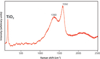
Figure 4: Raman spectrum of black shale consisting of contributions from kerogen and the anatase form of TiO2.
We noted earlier that one needs to exercise caution in comparing different Raman spectra of kerogen with differing degrees of maturity or diagenesis if one wants to use Raman spectroscopy to perform quantitative analysis of oil shale samples. The kerogen bands in Figures 4 and 5 demonstrate that need quite well. Upon initial inspection and comparison of the D-to-G band relative intensities seen in Figure 4 and the inset of Figure 5 it would appear that they differ. However, note that the background on the low-energy side of the Figure 5 inset is significantly greater than that of the corresponding region in Figure 4, thereby contributing to the appearance or false impression of a greater D-to-G band ratio in Figure 5 than in Figure 4. Therefore, to obtain a more accurate comparison of the relative band strengths for qualitative structural characterization and for quantitative analysis one should use a combination of background subtraction, followed by band fitting, and finally integration of the fitted peak areas. However, performing that exercise with precision is not trivial. In particular, a consistent approach to background subtraction is needed when one encounters a variety of spectral backgrounds because of different sources of luminescence among a set of oil shale samples. If quantitative analysis of oil shale by Raman spectroscopy is desired, an accurate and precise protocol of spectral background subtraction, band fit, and peak area integration are critical. This subject is perhaps worthy of more extensive treatment in another installment of "Molecular Spectroscopy Workbench."
The Presence of Titanium Dioxide of Different Crystal Forms
Aside from the differences in the kerogen Raman scattering, the other standout feature of the spectra in Figures 4 and 5 is the absence of calcite Raman bands and the presence of the sharp low-energy band that can be attributed to the A1gphonon of the anatase crystalline form of titanium dioxide. There are other crystalline forms of TiO2and one can easily mistake the brookite form for anatase because both polymorphs have strong, closely spaced low-energy Raman active bands at 153 cm-1 (A1g) (7,8) and 144 cm-1 (Eg) (6,7), respectively. Figure 5 shows a spectrum acquired from a location on the same sample of black shale; however, this region presumably consists primarily of TiO2in the laser focal volume with a relatively small amount of kerogen, as seen in the Figure 5 inset. Here, because most of the sample material in the laser focal volume consists of TiO2, all of the low-energy Raman bands are detected and strong enough to confirm, based on published reference spectra cited here, that this form of TiO2is indeed anatase and not the brookite form.
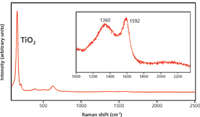
Figure 5: Raman spectrum from a black shale sample in which the laser focal volume consisted primarily of the anatase form of TiO2. The inset figure shows the relatively weak Raman scattering from kerogen.
As we saw earlier with various amounts of calcite in black shale, one can find variations in the relative amounts of anatase TiO2to kerogen. Raman spectra obtained from black shale at different locations are shown in Figure 6. These spectra clearly demonstrate the dramatic variability of kerogen Raman band structure observed in black shale along with the varying Raman signal strength of the anatase form of TiO2relative to that of kerogen. In this case, we have plotted all the spectra on different scales normalized to the Egband of anatase TiO2to more clearly see the differences among kerogen band positions and structure. Note that in one of the spectra the presence of quartz is confirmed by the appearance of the band at 463 cm-1. By generating reference samples of known amounts of kerogen and anatase TiO2, one could, in principle, use the relative Raman strengths to perform quantitative analysis of the black shale. However, one needs to exercise caution not only with respect to the proper state of kerogen reference, but also to the polycrystallinity or preferred orientation of single grains of TiO2in both reference and sample.
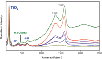
Figure 6: Raman spectra of black shale plotted on scales normalized to the Eg band of anatase TiO2. The differences in kerogen band shapes, widths, D- and G-peak separation and D-to-G intensity ratios relative to that of the normalized TiO2band indicate different structures of kerogen and relative kerogen-to-TiO2amounts, respectively. Also, note the 463 cm-1 band in one spectrum, thereby indicating the presence of quartz in the sample.
Anatase and brookite are not the only polymorphs of TiO2, another is rutile. The spectra shown in Figure 7 consist of Raman scattering from kerogen and the rutile crystal form of TiO2, thereby demonstrating the efficacy of Raman spectroscopy for differentiating crystalline forms of inorganic minerals. Raman spectroscopy is an effective alternative for inorganic oxide crystal phase identification in those instances in which the preferred method of X-ray diffraction is either impractical or not possible. Regarding the relative signal strengths of rutile TiO2and kerogen, we again see what upon initial inspection of the spectra would appear to be different relative amounts of rutile TiO2and kerogen. However, the upper trace has a luminescent background increasing with higher Raman shift, thereby giving the appearance of much stronger Raman scattering from kerogen than of TiO2. Therefore, a background subtraction followed by curve fitting and peak area integration is called for to more accurately compare the relative signal strengths of rutile TiO2-to-kerogen in these two sample locations.
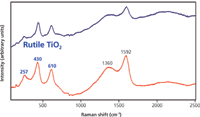
Figure 7: Raman spectra of black shale consisting of contributions from kerogen and the rutile form of TiO2.
Conclusions
Kerogen is defined as fossilized organic matter and as such consists mostly of carbon. Not surprisingly then, the spectrum of kerogen very much resembles that of amorphous carbon. The Raman spectra of kerogen have been analyzed and discussed within the context of the D (disorder) and G (graphite) band assignments of elemental carbon. The Raman spectra of black shale frequently consist of broad kerogen bands along with the much sharper bands at 156, 282, 714, and 1088 cm-1 attributed to crystalline calcium carbonate or calcite. Titanium dioxide is another polymorphic mineral found in oil shale rock. Various signal strengths of calcite or the anatase form of TiO2relative to that of kerogen were found in different samples of black shale presumably correlated to different relative amounts of kerogen-to-inorganic mineral. Titanium dioxide is known to exist in nature under different crystalline forms. Raman spectra revealed the presence of both anatase and rutile forms of TiO2in black shale.
References
(1) Ind. Eng. Chem. News Ed. 1(5), 2 (1923).
(2) Chem. Eng. News 35(34), 84–87 (1957).
(3) J. Jehlicka, O. Urban, and J. Pokorny, Spectrochim. Acta A 59, 2341–2352 (2003).
(4) D.S. Knight and W.B. White, J. Mater. Res. 4, 385–393 (1989).
(5) S.R. Kelemen and H.L. Fang, Energy & Fuels 15, 653–658 (2001).
(6) I.M. Clegg, N.J. Everall, B. King, H. Melvin, and C. Norton, Appl. Spec. 55, 1138–1150 (2001).
(7) G.A. Tompsett, G.A. Bowmaker, R.P. Cooney, J.B. Metson, K.A. Rodgers, and J.M. Seakins, J. Raman Spec. 26, 57–62 (1995).
(8) M.N. Iliev, V.G. Hadjiev, and A.P. Litvinchuk, Vib. Spec. 64, 148–152 (2013).
David Tuschel is a Raman applications manager at Horiba Scientific, in Edison, New Jersey, where he works with Fran Adar. David is sharing authorship of this column with Fran. He can be reached at david.tuschel@horiba.com

David Tuschel
A Proposal for the Origin of the Near-Ubiquitous Fluorescence in Raman Spectra
February 14th 2025In this column, I describe what I believe may be the origin of this fluorescence emission and support my conjecture with some measurements of polycyclic aromatic hydrocarbons (PAHs). Understanding the origin of these interfering backgrounds may enable you to design experiments with less interference, avoid the laser illuminations that make things worse, or both.
Raman Microscopy for Characterizing Defects in SiC
January 2nd 2025Because there is a different Raman signature for each of the polymorphs as well as the contaminants, Raman microscopy is an ideal tool for analyzing the structure of these materials as well as identifying possible contaminants that would also interfere with performance.