Time-of-Flight Mass Spectrometry for Proteomics Research
Special Issues
Time-of-Flight (TOF) is rapidly becoming the most popular method of mass separation for proteomics and conventional analytical chemistry. The development of very high temporal resolution ion detectors and low-cost high-speed digitizers has rendered this technique easily deployed and able to produce very high mass resolution. The performance of a TOF mass spectrometer is dependent upon a number of critical components. This article will focus on the ion detector.
Mass spectrometers are analytical instruments capable of identifying unknown materials in complex mixtures down to parts per billion. Once relegated to the research laboratories, mass spectrometers now are in use in a broad range of applications. They can be found screening for pesticides in canned foods, controlling semiconductor manufacturing processes, diagnosing disease, exploring for natural resources, discovering new pharmaceuticals, predicting volcanic eruptions, and in applications for securing our homeland. Indeed, these instruments have traveled beyond our world aboard the Galileo and Cassini spacecrafts to provide atmospheric analysis of neighboring worlds within our solar system. In fact one hardly can watch television or see a movie these days without hearing about mass spectrometers.
Time-of-flight mass spectrometry (TOF-MS) rapidly is becoming the most popular method of mass separation in analytical chemistry. The development of low cost digitizers and extremely fast ion detectors has fueled this popularity. TOF-MS is deployed easily, and can produce very high mass resolution. This technique of mass separation can be adapted for all forms of sample introduction and ionization. Unlike quadrupoles and ion traps, TOF mass analyzers perform well at very high mass such as with analyses of molecules frequently found in proteomic applications. Wiley and McLaren (1) in 1955 followed by Cotter (2) in 1992 and Wollnik (3) in 1993 have described TOF analyzers.
TOF mass spectrometers are produced in two main types - linear instruments and reflectron instruments.
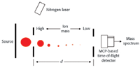
Figure 1. Cross section of a linear TOF instrument.
Linear TOF Mass Spectrometers
In operation, the unknown sample first is converted to ions. Figure 1 illustrates a typical MALDI (matrix assisted laser desorption ionization) instrument. The resultant ions then are injected into the flight tube where they begin traveling towards the detector.
The motion of the ions within the flight tube can be described by equation 1:

where m/z is the mass to charge ratio of the ion, d is the distance to the detector, and Vse is the acceleration potential.
The lighter ions (low mass) will travel faster, while the high mass ions will move to the detector more slowly. If the flight tube is long enough, all the ions will be arranged according to mass (smallest to largest) when the ions arrive at the detector.
When the ions arrive at the detector, they initiate a cascading of secondary electrons (4), this results in the generation of very fast voltage pulses, which precisely signal the arrival of the ions. A high-speed oscilloscope or transient recorder is used to record the arrival times. Figure 2 illustrates the arrival time spectrum of bradykinin collected on a linear TOF instrument.
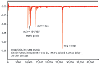
Figure 2. Mass spectrum of bradykinin.
Knowing the exact arrival times, equation 1 can be used to solve for the mass-to-charge ratio of the ions.
Reflectron TOF Mass Spectrometer
The second type of TOF mass spectrometer is the reflectron instrument. Figure 3 illustrates this design. The reflectron design takes advantage of the fact that the further the ions are allowed to travel, the greater the distance between ions of slightly differing masses. Greater distances between ions with different masses will increase the arrival time differences between the ions and there by increasing the resolution at which ions of a similar m/z can be differentiated. In addition, this design corrects the energy dispersion of the ions leaving the source (5).
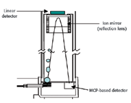
Figure 3. Reflectron TOF instrument.
In a reflectron analyzer, the ions are injected into the flight tube in the same manner as in a linear instrument. The ions traveling down the flight tube enter the reflectron lens. The electrostatic field created by applying separate high voltage potentials to each of the metal rings, slows the forward progress of the ions and eventually reverses their direction. They then exit the lens and are directed to the detector. This action effectively doubles the length of the flight tube, which improves mass resolution without adding any additional length to the flight tube.
The Reflectron Lens
The motion of ions in a reflectron lens has been described previously by Hoffman (5).
Most TOF instruments manufactured today incorporate reflectron analyzers. This device typically consists of a stack of alternating, precision ground metal rings and insulating spacers held together with threaded rods. This assembly may have hundreds of components which must be carefully assembled and aligned (typically by hand) in a clean, dust-free environment. Additionally, a voltage divider must be added to each row or layer in order to produce the electrostatic field gradient necessary to reverse the direction of the ion.
An advanced variant of this classical design utilizes a single resistive glass tube to form the field gradient replacing hundreds of discrete components.
Ion Detectors
One of the critical components of a TOF mass spectrometer for proteomics applications is the ion detector. Ion detectors are manufactured in three main types: microchannel plate (MCP), discrete dynode and continuous dynode (Chaneltron
®
). Modern high-performance TOF mass spectrometers used for proteomic research primarily utilize MCP-based detectors because of they have the largest collection area, the lowest time jitter, and the highest temporal resolution. Figure 4 illustrates some typical time-of-flight detectors manufactured by BURLE Electro-Optics.
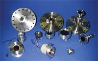
Figure 4. Various MCP-based TOF ion detectors.
The performance characteristics of the ion detector can have a profound effect on the performance of the mass spectrometer and the quality of the data produced. When selecting an ion detector, it is important to consider these key performance areas: gain, noise, temporal response, pulse shape, collection area, high mass sensitivity, positive and negative ion detection (bipolar), reliability, and serviceability.
The gain of the TOF detector is a measure of the amplification factor produced when an ion strikes the input surface. Most instruments today require a gain of at least 105-106. This means that a single ion will initiate a cascading of secondary electrons which result in a charge pulse of at least 1.6 Ã 10-13 coulombs. This signal level is sufficient to be recorded above the electronic baseline noise. Most Chevron (a detector containing two microchannel plates in series) detectors are capable of producing gains of 107-108. However, operating the detector at higher gains than necessary can reduce dynamic range and shorten the lifetime of the device.
The noise characteristics of the detector also are very important. Noise is defined as spurious output pulses which are not initiated by analyte ions. Because most spectra are created by averaging several "flights," occasional random pulses are removed from the data. Repetitive noise pulses at given intervals will appear as extra peaks in the spectrum, which can lead to some exciting times when your colleague announces they have "discovered" a new molecule.
Excellent temporal response of the detector is essential for high resolution and mass accuracy. If the detector is too slow, then different mass ions arriving at the detector which differ slightly in mass will appear to the instrument to have the same mass. The resultant peak produced from these two ions will be one broad peak rather than two narrow ones. Because the instrument assigns mass based on the centroid of the resolved peak, it will improperly identify the mass of the ion.
The best way to avoid this situation is to select an ion detector with a temporal response which is significantly faster than the gap in the arrival times for the ions. The highest temporal resolution detectors available today incorporate microchannel plates with extremely small pores. The ultrafast TOF instrument uses 2-μm pore microchannel plates and produce single-ion pulse widths of less than 350 ps. Increasing the speed of the detector improves mass resolution and reduces the required length of the flight tube, leading to smaller, less expensive instruments.
Detector manufacturers go to great lengths to design ion detectors with excellent raw pulse shapes. The ideal pulse shape is symmetrical, with the amplitude proportional to the abundance of the ions impinging on the detector. Frequently, however, these ideal pulse shapes are distorted by impedance mismatches in system hardware and electronics. In a typical TOF-MS system, the signal from the detector must travel 10 cm to the vacuum feed through, through the vacuum wall, and then up to 2 m to the instrument digitizer. Any impedance mismatch can cause distortion in the pulse shape leading to degradation in mass resolution and accuracy. Many experimenters attempt to fabricate detectors by assembling microchannel plates into hardware assemblies only to observe distorted pulses, which suffer from tailing and ring. Figure 5 shows examples of good and distorted pulses. Pulses are oscilloscope traces displayed in the raw form from the detector.

Figure 5. Examples of good and distorted pulses: (a) pulse reflection causes what looks like a second peak; (b) impedance mismatch causing ringing (2 ns/div.) (10 ns/division); and (c) raw ion pulse from a well matched detector and electronics package (500ps/div).
The active diameters for TOF detectors typically range from 8 to 75 mm. The active diameter of the ion detector need only be as large as the ion beam. Initially, ion detectors tended to be very large (40-75 mm) to capture the entire ion beam. As ion optics improved, the required collection area was reduced. Today the most widely used time-of-flight detector, the APD APTOF 18, has an 18-mm active diameter.
Proteomics research often times requires the analysis of high mass materials. Conventional TOF detectors loose detection efficiency as the mass of the ion increases. Laprade and Owens (6) have described in detail the development of a patented bipolar TOF detector that significantly increases the detection efficiency for high mass ions. In this device, the ions pass through a grid at the end of the flight tube and then are subjected to post acceleration using up to 10 kV before they collide with the microchannel plate and initiate the cascading of electrons. This detector also incorporates a low work function coating on the converting surface to further increase the detection efficiency.
Most mass spectrometers produce spectra using only positively charges ions. Although this is adequate for most applications, running a mass analysis in both the positive and negative ion modes frequently reveals valuable information about the structure of the original molecule that produced the ions. Detecting negative ions necessitates reversing the polarity of the detector and capacitively coupling the signal to the system digitizer.
The bipolar TOF detector utilizes electro-optical isolation in the form of a fast scintillator and photomultiplier tube to prevent the system digitizer from being exposed to the 10 kV post acceleration voltage. This unique structure makes it easy to detect positive or negative ions and eliminates the need for capacitive coupling the signal to the digitizer.
The active elements in a time-of-flight detector are not intended to last the life of the instrument. Periodically, the microchannel plates will need to be replaced with fresh ones. The service period will depend upon the types of samples analyzed. Discounting vacuum failures, a typical TOF detector used in a proteomic application should function for at least two years. Many manufacturers of TOF instruments now incorporate a cartridge design which enables the end user to easily replace the MCPs.
The future for mass spectrometry is a bright one. Teams from academia, national labs, and industry are hard at work on the next generation of instruments which promise even better performance and value. Driven by a near fever pitch of applications development in drug discovery, homeland security and energy exploration, these instruments will continue to improve our quality of life.
References
1. W.C. Wiley and J.B. McLaren,
Rev. Sci. Instrum.
26,
1150 (1955).
2. R.J. Cotter, Anal. Chem. 64, 1027A (1992).
3. H. Wollnik, Mass Spectrom. Rev. 12, 89 (1993).
4. B.N. Laprade, SPIE Proceedings, vol. 1655 (1992).
5. E. De Hoffmann, J. Charette, and V. Stroobant, Mass Spectroscopy Principles and Applications (Wiley, 1996).
6. B.N Laprade, R. Cochran, and K.G. Owens, poster 1415P presented at the 2002 Pittsburgh Conference. ?
Bruce N. Laprade is director of Engineering and Quality Assurance for BURLE Electro-Optics, Inc. (Sturbridge, MA). Phone: (508) 347-4044. E-mail: lapradeb@ burle-eo.com

High-Speed Laser MS for Precise, Prep-Free Environmental Particle Tracking
April 21st 2025Scientists at Oak Ridge National Laboratory have demonstrated that a fast, laser-based mass spectrometry method—LA-ICP-TOF-MS—can accurately detect and identify airborne environmental particles, including toxic metal particles like ruthenium, without the need for complex sample preparation. The work offers a breakthrough in rapid, high-resolution analysis of environmental pollutants.
The Fundamental Role of Advanced Hyphenated Techniques in Lithium-Ion Battery Research
December 4th 2024Spectroscopy spoke with Uwe Karst, a full professor at the University of Münster in the Institute of Inorganic and Analytical Chemistry, to discuss his research on hyphenated analytical techniques in battery research.
Mass Spectrometry for Forensic Analysis: An Interview with Glen Jackson
November 27th 2024As part of “The Future of Forensic Analysis” content series, Spectroscopy sat down with Glen P. Jackson of West Virginia University to talk about the historical development of mass spectrometry in forensic analysis.
Detecting Cancer Biomarkers in Canines: An Interview with Landulfo Silveira Jr.
November 5th 2024Spectroscopy sat down with Landulfo Silveira Jr. of Universidade Anhembi Morumbi-UAM and Center for Innovation, Technology and Education-CITÉ (São Paulo, Brazil) to talk about his team’s latest research using Raman spectroscopy to detect biomarkers of cancer in canine sera.