Tutorial — Mass Analyzers: An Overview of Several Designs and Their Applications, Part I
Spectroscopy
This tutorial illustrates the technical principles and typical applications of the most common mass analyzers used in bioanalytical laboratories today, as well as novel techniques and mass analyzer designs. Examples are based upon the authors' research in small molecule applications.
Mass spectrometry (MS) instrumentation has undergone several improvements over the years, including increased sensitivity, ease-of-use, and possibilities for more sophisticated and time-efficient experiments. These developments have led to an increase in the number of biological applications. In the 1990s and until recently, new instrumental innovations in organic MS had focused mainly upon front-end techniques — ionization interfaces specifically. In particular, electrospray ionization (ESI), atmospheric-pressure chemical ionization (APCI), and matrix-assisted laser desorption–ionization (MALDI) have evolved from these developments and have seen significant performance improvements over the years. Along the way, a few other interesting liquid chromatography–mass spectrometry (LC–MS) interfaces (for example, thermospray, particle-beam) have paved the way for modern LC–MS, but have then disappeared quickly from research laboratories. Also, a promising new ionization source, atmospheric-pressure photoionization (APPI) was introduced just a few years ago. As a result of all these innovations, rather good and stable MS sample introduction devices are available for a wide range of compound classes and most researchers seem quite satisfied with what they presently have available at their disposal. Continuing research on these ionization sources currently is aimed at enhancing the performance of such devices, through miniaturization, automation, and parallel-analyses. Lately, however, MS instrumentation research is dominated by improvements in the performance of the actual mass analyzers. Moreover, there is a growing trend toward combining different analyzer designs in order to increase the versatility and allow multiple experiments to be performed simultaneously using a single instrument. One of the most recent examples of such a novel hybrid instrument is the linear ion trap-Fourier transform ion cyclotron resonance mass spectrometer (LIT-FT-ICR), which will be discussed subsequently in more detail. This instrument allows fast, multistage tandem MS (MS-MS) experiments as well as ultra-high resolution and accurate mass determinations. The driving force behind this recent trend of improving analyzer designs mainly has been scientists from biotechnology and pharmaceutical research laboratories. Their time is costly and their analytical protocols now routinely include the use of multiple MS instruments.
This article illustrates the technical principles and typical applications of the most common mass analyzers used in bioanalytical laboratories today. The classical mass spectrometer — the magnetic sector instrument — is not covered by this tutorial. Although these instruments allow very selective scan modes, their implementation is much less routine and is beyond the scope of this article. Moreover, magnetic sector instruments seem to have reached the apex of their technological development, while improvements in instrument technologies based upon other mass analyzers continue to evolve and develop in new directions. Magnetic sector instruments still are employed for specialized analyses, for example, in the petroleum industry or for the analysis of dioxins by gas chromatography–mass spectrometry (GC–MS).
There are four basic types of mass analyzers found in modern MS: time-of-flight (TOF), quadrupole and a recent derivative, quadrupole linear ion trap (LIT), quadrupole ion trap (QIT), and FT-ICR. The first part of this article will cover TOF and quadrupole analyzers; Part II will address QIT and FT-ICR. More interestingly, however, there are several very advanced permutations of these analyzers, which through the combination of different analyzers create enhanced MS-MS capabilities, novel scan modes, or superior mass resolution and accuracy. For example, the quadrupole-time-of-flight (QqTOF) instrument has developed into one of the most successful hybrid MS designs, allowing the generation of triple quadrupole–like MS–MS spectra, combined with high resolution and accurate mass capability in the TOF analyzer. This combined potential, together with flexible data-dependent acquisition routines, has been proven to be of significant importance for proteomics MS. Rather than just explaining the underlying physical principles, we will concentrate on their characteristic features, their limitations, and their applications (more details, in particular on the fundamental operating principles, can be found in textbooks on mass spectrometry; for example [1]). In addition, several unique techniques and unusual or exotic mass analyzer designs are highlighted throughout the text. We have chosen all of the examples from our own research; as a result, this overview is biased toward applications to small molecules. Therefore, some interesting recent hybrid designs with mostly proteomics applications, such as ion trap-TOF, only are described briefly.
The Time-of-Flight Analyzer
A linear TOF mass spectrometer is the simplest mass analyzer that exists today, consisting only of an ion-accelerating region, a flight tube, and a detector. These linear instruments are used primarily in combination with the MALDI technique for analysis of large biomolecules. In theory, all ions experience the same potential difference during acceleration and thus have the same kinetic energy at the start of the flight tube, and thus different velocities depending upon their mass. Therefore, their arrival time at the detector is proportional to their mass and they reach the detector in order of increasing mass. The mass-to-charge ratios (m/z) of the ions relate to the flight times t by the following equations:


where l is the length of the flight tube, v is the velocity of the ion of mass m and charge z, and V is the acceleration potential. For example, the electrosprayed antibiotic ciprofloxacin (MW = 331 g/mol; MH+ at m/z 332) arrives at the detector 9.3 μs after being accelerated with 20 kV into a 1-m long flight tube, whereas the much heavier singly protonated bovine insulin molecule (m/z 5734) needs 65.1 µs to reach the end of the tube. These flight times translate into the m/z values via Equation 2. The differences of flight times are, of course, the basis for resolving ions of different m/z in the TOF analyzer and the mass resolution depends on the flight time differences, which are proportional to l(√m1 – √m2).
The major deficiency of a simple linear TOF instrument is its insufficient mass resolution, resulting from flight time variations of ions of the same m/z. First, the laser pulses used for ion generation in MALDI-TOF instruments are fairly long, resulting in a wide distribution of starting times of the same ions. Further, the ionization process adds a certain amount of initial kinetic energy to the molecules before acceleration. Finally, the different spatial positions in the source from where the ions are formed lead to varying values of l (Equation 2) and thus to flight time variations. As a result, modern TOF instruments commonly employ two techniques to enhance resolution, reflectrons and delayed extraction (for MALDI-TOF).
A reflectron TOF (RETOF) is used to focus ions of the same m/z but of different kinetic energy. There are different designs of reflectrons but often they consist of a series of rings or grids. It is located after the drift tube, creating a retarding field that the ions penetrate. Depending upon their kinetic energy, they enter this field at different depths and then are reflected back into the flight tube, where they drift to the detector, which is placed close to the ion source. Consider the case of ions of the same m/z but significant energy spread, which would be detected as broad peaks in the linear TOF: the ion with a higher kinetic energy penetrates deeper and spends more time in the reflectron. The slow ion, on the other hand, returns to the flight tube faster, but with the same lower kinetic energy. The faster ion will catch up with the slow one at the detector, thereby improving mass resolution greatly.
The delayed extraction technique can be used on both linear and RETOF instruments, to compensate for the velocity distributions of ions. In this technique, which also is sometimes called time-lag focusing or pulsed ion extraction, ions are allowed to drift free of electric fields after formation for a certain delay time. The ions then are accelerated into the flight tube. By allowing them to drift, faster ions move farther away from the sample target than the slower ions. After the delay, these faster ions then will experience less of the accelerating voltage between the sample target and the extraction plate than the slow ones. This procedure compensates for the initial energy distributions of ions with the same m/z.
There are several benefits that TOF analyzers offer when combined with ionization sources such as electrospray or MALDI. In addition to the high mass range that can be analyzed (with a linear TOF instrument) and the high ion transmission, there is the unique advantage of quasisimultaneous detection of all ions, resulting in high sensitivity "full-scan" analyses (of course, the term "full scan" obviously is wrong in the context of TOF-MS, as a TOF-MS is not a scanning device, but the common terminology is used here for the sake of convenience). Thus, they are ideal in qualitative applications such as the identification of unknown compounds, in which the acquisition of an entire mass spectrum is required. Figure 1 shows an example for the analysis of metabolites of an anticancer drug, analyzed on an ESI-TOF instrument, demonstrating the high resolving power and mass accuracy of a TOF analyzer. In addition, TOF analyzers exhibit very fast acquisition times and thus are ideal for hyphenation with capillary electrophoresis and fast LC. Of course, the pulsed nature of TOF analysis makes the hyphenation with a continuous ion source such as electrospray more difficult than with MALDI, which inherently is compatible with TOF analysis. The necessary "slicing" of the ion beam coming from the ESI source can be performed axially or orthogonally. For organic LC–MS, the design is usually an orthogonal acceleration (oa) TOF type. The ions are focused into the orthogonal accelerator as a narrow ion beam and a slice of it is pushed down into the TOF tube. The amount of ions entering the TOF tube (that is, the length of the "slice") relative to the total amount of ions in the orthogonal accelerator determines the duty cycle of the instrument (see the sidebar "Duty Cycle in MS" for further explanation). After the heaviest ions have reached the detector, the next pulse pushes another slice of ions into the drift tube.
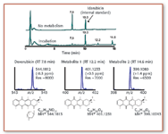
Figure 1. Metabolism of doxorubicin in mouse liver microsomes was analyzed by ESI-TOF for the determination of accurate masses of the metabolites formed in vitro. Idarubicin was used as an internal standard in this experiment and two main metabolites were characterized with the aid of the high resolution afforded by the TOF mass analyzer (with internal calibration).
The downside of TOF applications is the limited dynamic range; that is, the ratio of the maximum to the minimum observable ion intensities or concentrations over which a linear response is obtained from the detector. This is the direct result of the types of detectors that are employed for handling the large number of high-resolution spectra, making the application of TOF instruments to quantitative analyses less attractive. There is another weakness encountered with TOF analyzers: it is technically difficult to select a precursor ion for MS–MS experiments. In MS–MS, a specific precursor ion is isolated and then made to undergo dissociation to fragment ions, which are analyzed subsequently to obtain structural information. It is important for the precursor ion of interest to be isolated from interfering species; in other words, one needs to be able to select a very narrow m/z range. In a RETOF instrument, a TOF gate can provide only a very coarse precursor selection (over several m/z units wide), to study metastable compositions. This technique is used in combination with postsource decay (PSD) and is quite popular for sequencing of peptides.
Duty Cycle in MS
It is much more elegant, however, to utilize a separate mass spectrometer for precursor ion selection, allowing the isolation of a single m/z value. One option is to use another TOF drift tube together with a time selector, and such a design is available commercially for specialized proteomics applications (see the sidebar "TOF–TOF Instruments for High Energy CID"). Much more common, however, is the implementation of a quadrupole mass filter prior to the TOF tube. In fact, this can be taken one step further, by adding a second, radio frequency (rf)-only quadrupole as a collision cell (Q1 q2 TOF). The TOF analyzer then is used to provide accurate mass data for fragment ions formed in q2 . Before we describe the QqTOF instrument, however, we will take a look at the basic operating principles of a quadrupole.

TOFâTOF Instruments for High-Energy CID
The Quadrupole Mass Analyzer
The quadrupole is the most common analyzer found in analytical laboratories today. It is not only the standard analyzer for GC–MS (which will not be discussed here) but also is part of various designs of LC–MS instruments. Quadrupoles are not used only as mass analyzers; they also are implemented frequently as ion transfer optics, collision cells, and linear ion traps (vide infra). This mass analyzer works on the basis of electric fields generated between a set of four axial rods through which ions pass on their way to the detector. The voltages applied to these rods consist of direct current (dc) and rf components, which together create a quadrupolar field, allowing only a certain m/z range to pass through for a given combination of potentials; ions outside that m/z region hit the rods and are discharged. The quadrupole therefore is referred to also as a mass filter, into which ions are accelerated from the ion source by a small potential. Positive ions will be attracted to negative rods, and vice versa. The rf component, however, causes the electric field to alternate at a frequency in the megahertz range. The applied potential to the rods is of the form:

where U is the dc voltage and Vcos ωt is the rf potential of frequency ω/2π. Two rf waveforms are applied to two pairs of opposing parallel rods, with a 180° phase shift. As a result, the trajectory of an ion fluctuates constantly as it travels between the rods until its detection.
In a full-scan experiment, the dc and rf components are ramped at a constant ratio, and ions entering from the ion source are enabled to pass through the rod assembly successively. For a specific combination of dc and rf, only a very small m/z range can pass through, the size of which determines the resolution of the instrument. Quadrupoles usually are operated at unit resolution throughout the mass range (often up to m/z 4000), allowing the separation of m/z 150 and 151 or m/z 1500 and 1501, for example. Higher mass resolution, however, is available on a recent commercial quadrupole instrument produced by Thermo Electron (Waltham, MA). The sequential detection in the full-scan mode of any quadrupole analyzer results in a low duty cycle, typically of the order of 0.1%, depending upon the monitored m/z range. The duty cycle (and the resulting sensitivity) is much higher in the selected ion monitoring (SIM) mode of the quadrupole (close to 100%). In this case, the dc and rf potentials are held constant, so only a specific m/z ratio can pass through. One also can jump between different voltages, to allow more than one m/z ratio to be detected sequentially, with a corresponding reduction in duty cycle.
Single quadrupole instruments usually are limited to measuring intact species generated by the ionization source, resulting in limited selectivity in comparison to many of the advanced designs described in the following. They have, nevertheless, found a wide application range in LC–MS and GC–MS. Such instruments often are considered more of a selective HPLC detector today than a mass spectrometer. Typical applications of single quadrupoles include purity assessments, molecular weight confirmations, and automated preparative HPLC fractionations. Figure 2 shows an example for a mass-triggered fractionation experiment from a semipreparative HPLC run, where a single quadrupole was used to supply trigger signals to the fraction collector, to start collecting the chromatographic peaks of interest.
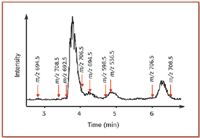
Figure 2. Mass-triggered fractionation chromatogram using a single quadrupole instrument set-up with specific m/z values for triggering the fraction collector. A crude phytoplankton extract was purified into several fractions for further analysis of marine toxins by mass spectrometry. Arrows above show the start of individual triggers (with the m/z responsible for the trigger).
In a single-quadrupole instrument operating with an ESI or APCI source, selectivity can be increased when fragmentation is induced in the ion source region ("in-source CID"). This procedure refers to the activation of ions in the region between the ion source and the analyzer, in which fragmentation can be initiated by collisions with residual gas molecules at intermediate pressures. The generated fragment ions can be used for limited structure elucidation or confirmation purposes. One must be careful, however, as no precursor ion selection takes place and fragment ions cannot be linked specifically to the precursor ion of interest. In other words, fragment ions could originate from several compounds for coeluted peaks in LC–MS, making structure assignments difficult (similarly, quantitative analysis in the SIM mode would be difficult when isobaric interferences contribute to the chromatographic peaks).
The most common mass analyzer for quantitative bioanalytical analyses is the triple quadrupole. This MS–MS instrument consists of three sequential quadrupoles (Q1 q2 Q3 ; Q refers to a mass-resolving quadrupole, q to an rf-only quadrupole; vide infra). This configuration allows additional ion activation in q2 , after the ion of interest has been selected in Q1 . The second quadrupole q2 is operated in the rf-only mode, in which only an rf voltage is applied to the quadrupole rods (no dc component), thus effectively becoming a wide-band pass for the ions. It can be filled with a neutral gas such as N2 or Ar, acting as a collision gas. The ions leaving Q1 are accelerated into q2 with offset voltages between 0 and 100 V, typically. The results of the collision-induced dissociation (CID) can be analyzed with the mass analyzer Q3 . This is the simplest form of an MS–MS experiment on a triple-quadrupole mass spectrometer, and it is called a product ion scan. In addition, several other selective MS–MS modes are available, depending upon which mode Q1 and Q3 are used in (see Table I).

Table I.
The precursor ion scan essentially is the reverse of the product ion scan. The third quadrupole is set to select a specific product ion formed in q2 , and the first quadrupole is scanned for all precursor ions forming the chosen fragment. An important use for precursor ion scans is seen in the pharmaceutical industry, for the identification of drug metabolites with similar fragmentation behavior to that of the parent molecule. A neutral loss scan experiment also is achieved in this instrument with relative ease. Neutral loss scans are used routinely to identify common functional groups present in a set of molecules. Figure 3 shows one of the most common applications conducted with triple-quadrupole instruments, the quantitative analysis of drugs and their metabolites in biological specimens such as plasma or urine. In these analyses, the MRM mode is almost always applied, allowing enhanced sensitivity and selectivity by circumventing isobaric interferences from the biological material. The experiment shown in this example actually was run on a QqLIT instrument, where the third quadrupole is replaced by a linear ion trap (see below). For MRM analyses, however, both these instruments function in the same manner.
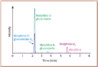
Figure 3. Representative chromatogram from a human serum sample after administration of morphine. The following MRM transitions were monitored for quantitation of the parent drug and its two glucuronide metabolites: morphine (m/z 286â201), morphine-d3 (internal standard, m/z 289â201), morphine-3-glucuronide and morphine-6-glucuronide (m/z 462â286), and morphine-3-glucuronide-d3 (internal standard, m/z 465â289).
Interestingly, in addition to their function as collision cells, rf-only quadrupoles also are widely used as ion transfer optics. In that application, ions passing through the quadrupole are confined in the center of the quadrupole axis at low gas pressures, thus increasing transmission efficiency. Often, other multipoles such as hexapoles or octopoles are used for the same purpose. This effect is called collisional cooling or collisional focusing. Furthermore, by adding trapping electrodes at the beginning and the end of such a quadrupole, one can store ions in the device. These linear ion traps have become very popular recently, either as a stand-alone MS or as front-end stages prior to FT-ICR, or as Q3 in a triple-quadrupole MS. Among several other scan modes, the QqLIT design allows an additional stage of MS-MS after the regular triple-quadrupole CID. Figure 4 shows an illustrative example of how a QqLIT can add complementary information to the regular CID analysis in q2 . There is, however, a catch to these experiments: trapping ions in a LIT takes quite a bit of time, in comparison to the residence time of ions in a regular QqQ instrument. For the QqLIT instrument, that would result in a significantly reduced duty cycle when additional MS3 experiments are performed in the LIT, because it requires some time for the resonance excitation to take place (typically 50–200 ms). During that time, ions coming from q2 would be lost. If we trap the ions in the meantime, however, and transfer the ion bundle into Q3 only after the MS3 experiments in Q3 are finished, we would not lose any ions, and duty cycle would be restored. In the commercial QqLIT instrument, this is achieved by storing the ions temporarily in a focusing quadrupole (before the QqQ; the manufacturer calls it q0 ).
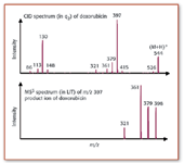
Figure 4. The MS3 spectrum of doxorubicin above was performed using a QqLIT instrument. Secondary fragments of the product ion at m/z 397 are shown in the lower trace and give information on the fragmentation pathways of this anticancer drug. Note that the ion at m/z 398 is due to the isolation of the M+1 isotope peak of m/z 397 in the LIT, without subsequent excitation by on-resonance CID, therefore it is still in the linear ion trap when the MS product ions are detected.
Finally, one also can replace Q3 with a completely different mass analyzer, in particular, with a high-resolution device. This makes a lot of sense, because it allows the acquisition of accurate mass data for fragment ions. The most common hybrid system is the quadrupole-quadrupole-time-of-flight (QqTOF) MS. The coupling of the Qq section and the TOF system is achieved in exactly the same way as described in the previous section for ESI-TOF, that is, by adding an orthogonal acceleration region after the collision cell. The TOF section now serves only to record spectra, with high resolution and high mass accuracy. QqTOF systems were developed originally for peptide sequencing applications, but also are now applied routinely for the accurate mass determinations of small molecules; for example, for confirmation of tentatively identified metabolites during the drug discovery process. An example for the QqTOF characterization of fragment ions formed from CID analysis of a protonated biotoxin molecule is shown in Figure 5.
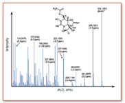
Figure 5. Product ion spectrum of neosaxitoxin on a QqTOF instrument. The experimental m/z values for several product ions are shown above with their corresponding mass accuracies, measured in parts per million (ppm) (note that the mass accuracy is the difference between the measured accurate mass and the calculated exact mass. It is often expressed in relative terms, ppm).
References
1. J.H. Gross, Mass Spectrometry (Springer, Berlin Heidelberg, 2004).
2. I.V. Chernushevich, Eur. J. Mass Spectrom . 6, 471 (2000).
3. R.N. Zare, F.M. Fernandez, and J.R. Kimmel, Angew. Chem. Int. Ed . 42, 30 (2003).
4. O. Trapp, J.R. Kimmel, O.K. Yoon, I.A. Zuleta, F.M. Fernandez, and R.N. Zare, Angew. Chem. Int. Ed . 43, 6541 (2004).
Dietrich Volmer is a senior research scientist at the Institute for Marine Biosciences in Halifax, Nova Scotia, Canada. Lekha Sleno is a Ph.D. student in Dr. Volmer's group. E-mail: Dietrich.Volmer@nrc-cnrc.gc.ca

High-Speed Laser MS for Precise, Prep-Free Environmental Particle Tracking
April 21st 2025Scientists at Oak Ridge National Laboratory have demonstrated that a fast, laser-based mass spectrometry method—LA-ICP-TOF-MS—can accurately detect and identify airborne environmental particles, including toxic metal particles like ruthenium, without the need for complex sample preparation. The work offers a breakthrough in rapid, high-resolution analysis of environmental pollutants.
The Fundamental Role of Advanced Hyphenated Techniques in Lithium-Ion Battery Research
December 4th 2024Spectroscopy spoke with Uwe Karst, a full professor at the University of Münster in the Institute of Inorganic and Analytical Chemistry, to discuss his research on hyphenated analytical techniques in battery research.
Mass Spectrometry for Forensic Analysis: An Interview with Glen Jackson
November 27th 2024As part of “The Future of Forensic Analysis” content series, Spectroscopy sat down with Glen P. Jackson of West Virginia University to talk about the historical development of mass spectrometry in forensic analysis.
Detecting Cancer Biomarkers in Canines: An Interview with Landulfo Silveira Jr.
November 5th 2024Spectroscopy sat down with Landulfo Silveira Jr. of Universidade Anhembi Morumbi-UAM and Center for Innovation, Technology and Education-CITÉ (São Paulo, Brazil) to talk about his team’s latest research using Raman spectroscopy to detect biomarkers of cancer in canine sera.