Classical Least Squares, Part III: Spectroscopic Theory
The authors continue their ongoing discussion of classical least squares with a look at spectroscopic theory.

In our two previous columns in this (sub)series (1,2), we examined the mathematics behind the classical least squares (CLS) approach to analysis. This approach is based upon the fact that when Beer's law applies, as in clear liquids, the spectrum of a mixture is the sum of the spectra of the individual pure components, each weighted by its concentration.

Howard Mark
What we saw in those actual spectra was that while the mathematics describing the spectra is exact, the synthesis of the mixture spectra, and the recovery of the pure component spectra from a set of mixtures, was approximately correct, but not exactly correct.
There are two reasons for the discrepancies we found. One reason was the nature of the optical measurement used for obtaining those spectra. While the samples were measured in a temperature-controlled cell, the optical measurements were made by transflectance. Thus, while the incident beam from the spectrometer was fully directed and specular, the beam was returned to the spectrometer for measurement by diffuse reflectance. A consequence of this measurement technique is that the returning rays, after diffuse reflection, are spread out through a wide range of angles.
We have demonstrated previously an effect on rays passing through a sample at a high angle to the normal (3) (or see chapter 29 in [4]). We summarize the effect here by noting that because those rays at high angles have a longer pathlength through the sample than rays that pass through the sample perpendicular to the faces, they are more strongly absorbed. The net effect is to introduce a nonlinearity in the spectroscopic response, and the nonlinearity is greater at high absorbances, an effect we have also previously demonstrated (see reference 3 or chapter 27 in reference 4).

Jerome Workman, Jr.
The second reason for the discrepancies is the interactions between water, methanol, and acetic acid. All three of these materials contain the OH functional group. This functional group can dissociate or form hydrogen bonds. Furthermore, there is a very delicate equilibrium between undissociated –OH, and varying amounts of hydrogen bonding between the three materials. The wavelength at which hydrogen absorbs depends strongly upon its environment, and the change from undissociated –OH and hydrogen bonded –OH causes changes in the absorbance properties of the species, both in strength and wavelength. Thus, mixing these materials together created conditions whereby the absorbances change as the proportions of materials in the mixture change. An example is shown in Figure 1, where spectra of water–methanol mixtures are shown. In these mixtures, the amount of water varies between 0% and 100% in uniform 25% steps. It is clear, especially in the spectral region around 2270 nm, that the spectra are compressed at the higher absorbances.
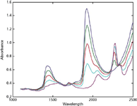
Figure 1: Spectra of waterâmethanol mixtures varying from 0% water to 100% water in equal steps of concentration.
The equations for the CLS computations assume that all the spectra respond in a strictly linear fashion to concentration, and add together in exact proportion to their concentrations. As we have seen, however, there are at least two physical causes of nonlinearity in the spectra of the mixtures of these three materials that we were working with, an optical effect and a perturbation of the spectra when the environment is changed. It should come as no surprise, therefore, to find that the equations that depend upon strict linearity in the behavior of the analytes don't properly describe the system formed, when applied to the mixtures where strict linearity is not present. It is the lack of linearity, resulting from distortions of the spectra of the components (due to interactions with the other components) that caused the differences between the spectra of mixtures calculated from the pure materials and the actual mixture spectra, as well as the imperfect recreation of the spectra of the pure materials from the spectra of the mixtures.
To demonstrate that the CLS approach can, in fact, actually work as described, we will need to start over again, and use materials that will not interact the way water, methanol, and acetic acid do. Before doing that, however, we also will describe the CLS method in a way that (we hope) will be more meaningful to a spectroscopist than the descriptions we used previously (1,2), which were intended for more mathematically and chemometrically oriented practitioners. Then we'll examine the results of using toluene, n-heptane, and dichloromethane as the three liquids, these being all hydrocarbons with no –OH or other functional groups. We also will see that the measurements are made in transmission, so that the nonlinearities attendant upon the use of transflection are not operative. So now we'll begin approaching this by presenting the same algebraic equations we saw before, but we will look at them as a spectroscopist would, not as a statistician or chemometricians would. Because we are still talking about Beer's law, we again begin with the equation for Beer's law:

As we described previously, equation 1 applies wavelength-by-wavelength, and tells us that at any given wavelength, the absorbance (A) is proportional to the absorptivity (a) of a material at the chosen wavelength, the pathlength of the light through the material (b) and the concentration of the material (c). The absorptivity (a), of course, is the implicit property of a molecule that varies with wavelength, and thereby constitutes the "spectrum" of that molecule. Because the pathlength is often, in practice, a quantity fixed by the cell that contains the sample, and is certainly the same for all components of a sample being measured, it is convenient to combine it with a and consider the product ab as the quantity we are measuring.
Equation 1 applies to a single component in a sample. When there are multiple absorbing components, the total absorbance is the sum of the absorbances of all the absorbing materials, at the wavelength of interest. Because this happens at every wavelength, we also speak of the spectrum of a mixture, that is, the absorbance at every wavelength, as being the sum of the spectra of the components of the mixture, each one weighted by its concentration.
Equation 1 was derived for, and therefore applies to, measurements made in transmission when the sample is a clear (that is, nonscattering) liquid. The presence of scattering enormously complicates the situation, to the point where it is still considered an unsolved problem despite the extensive efforts of many scientists over the years (5–9) and the more recent work of Don Dahm (10) for typical examples.
The "inverse" Beer's law case, as it is sometimes called, is derived from equation 1 by the simple expedient of dividing both sides of equation 1 by the ab product, thereby solving the equation for c, as we saw in reference 2:

In this form, we have previously described how the relationship between the absorbance and analyte concentration can be found using least squares calculations (11).
Anyone reading the previous explanations will be (or at least should be) asking themselves, "So what's the difference between the "inverse" least squares and the "classical" (or "direct" least squares) methods? They're both least squares, aren't they?
The answer is "Yes, but . . . ." We continue by presenting some matrix equations, without attempting to understand them, at this point.

Table I: Matrix equations comparing CLS and ILS calibration algorithms
In Table I, the symbols have the following meanings:
C = concentration of analyte(s) *
A = Absorbance spectrum of sample(s) **
b = coefficients of absorbances at the given wavelengths ***
S = Absorbance spectra of pure materials ***
*In inverse least squares (ILS), [C] represents the concentration of the analyte for which a model is being developed; in CLS, [C] represents the concentrations of all the pure materials comprising the sample.
** Similarly, in ILS, [A] represents the absorbance of the samples comprising the calibration mixtures, while in CLS, [A] represents the absorbance spectrum of the sample being analyzed.
*** Note that b (the coefficients of selected wavelengths) and S (spectra of pure materials) do not have exact counterparts in the other calibration algorithm, although in a loose way, the spectrum of a pure material could be viewed as "coefficients" representing the absorbance that material at the various wavelengths.
A casual inspection of the two equations in Table I probably would elicit the reaction "But except for the positions of the labels S and A, those two equations look practically the same!"
Yes, indeed they do. There are corresponding parts to the two equations, [SST]-1 corresponds to [AT A]-1, ST corresponds to AT, and [C] on the CLS side corresponds to [b] on the ILS side. These correspondences are due to the fact that both equations represent a "least squares" calculation of the data. So what's the difference? The equations seem to do the same things. Because they both specify the computation of least squares, they are doing the same things. In fact, without going into all the gory details, the two equations are, in reality, the inverse case of each other. But then, don't they say to do the same things, regardless of the label used to represent the variables?
The answer is "not exactly." The difference between the two equations becomes more apparent when you realize that, first of all, those equations in Table I are matrix equations (as we stated initially, just before we presented the equations) and that while matrix operations sometimes appear to reflect algebraic equations, there are differences between matrix operations and similar-looking algebraic equations.
In the case of the equations in Table I, the pertinent rule for matrix operations is that matrix multiplication does not commute, that is, given two matrices [A] and [B], the matrix product [A] [B] does not, except under very special conditions, equal [B][A]. Therefore, it's not just a matter of the labeling. Even if A and S were to represent the same quantities (which they don't despite the fact that they both represent absorbances), the product AT [AAT]-1 would not equal [AAT]-1 AT, for example.
We have previously examined the case of ILS in earlier columns (11,12), so let us now concentrate on the "classical" least squares methodology, to see how it differs. Again, we come back to the fact that "classically," chemists learned to do chemical analysis using spectroscopy by thinking about spectra the way they were taught to do.
So how do chemists think about spectra? To answer this question, let's look at Figures 2a and 2b. Figure 2a shows the absorbance spectra of some pure liquids: dichloromethane, toluene, and n-heptane. The reasons for the choice of these materials were mentioned briefly earlier, and also will be discussed further, in due course.

Figure 2: (a) Absorbance spectra of pure dichloromethane, n-heptane, and toluene (x-scale in wavenumbers) and (b) absorbance spectra of pure dichloromethane, n-heptane, and toluene, and of a ternary mixture of the three (x-scale in wavenumbers). Note that the baselines of the spectra are offset for clarity.
When chemists get their first exposure to spectroscopy, it is normally explained in terms of transmission measurements through clear liquids, and they start by learning a few basic "ground rules" about those measurements:
I. The presence of absorbance bands in the material, and their wavelengths, is characteristic of the nature of the material.
II. The strength of a given absorbance band depends on three factors:
- The absorptivity of the material at that wavelength, which is an inherent property of the material.
- The pathlength of the light through the sample.
- The concentration of the analyte in the sample.
III. The total absorbance of a sample, at a given wavelength, equals the sum of the absorbances, at that wavelength, of all the materials in the sample.
Let us make the point now that in the discussion to follow, all references to samples, spectra, and every other aspect of the discussion is based upon the paradigm of transmission measurements through clear liquid samples.
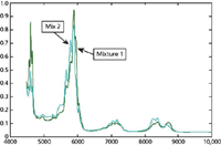
Figure 3: Spectra of two mixtures. Mixture 1 (blue): toluene = 50%, dichloromethane = 25%, n-heptane = 25%. Mixture 2 (black): toluene = 25%, dichloromethane = 50%, n-heptane = 25%.
For clear liquid samples, these properties of spectral measurements are universals, that is, they are valid for any sample and any wavelength, regardless of the underlying physics creating the absorbance properties of the material. Thus, for example, the same considerations apply whether the measurement is made in the UV range, where the underlying absorptions are due to the interactions of photons with the electronic atomic and molecular orbitals, or in the infrared range, where the underlying absorptions are due to interactions of light with the vibrations of the nuclei of the atoms comprising the sample.
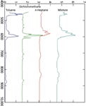
Figure 4: Absorbance spectra of pure dichloromethane, n-heptane, and toluene, and of a ternary mixture of the three (x-scale in wavenumbers). Note that this graph is identical to the graphs in Figure 1b except that it has been turned on its side by rotating it 90°.
Later, when we have become more sophisticated about these matters, we learn some new rules, such as the need to avoid interactions between different species present in the sample, and so forth. But for now, let's keep things simple and basic, and just consider the basic rules we stated earlier.
From rule 2 earlier, we learn about Beer's law. Without going into detail, we learn that there is a quantity call the absorbance (abbreviated A) that, at every wavelength, is the product of the three quantities listed: the absorptivity, the pathlength, and the concentration of the analyte. A way to see a convenient mnemonic is again to rewrite equation 1, as we do here:
A = abc
where:
A is the absorbance of the analyte at a specified wavelength,
a is the absorptivity of the analyte at that wavelength,
b is the pathlength of the light through the sample, and
c is the concentration of the analyte.
There are also some truisms that quickly become apparent. For example, a, the absorptivity at a given wavelength, is a constant of nature. Therefore, it is not under our control and for quantitative purposes, we simply have to accept those values that nature provides for us. On the other hand, there is a benefit to this. Because the absorptivity at a given wavelength depends upon the underlying molecular structures, the absorptivity is characteristic of those structures, and for qualitative purposes, the structure of the absorptivities, reflects the structure and properties of the underlying molecules, giving us, the users, the ability to identify those structures. This is an area of spectroscopy that has been highly developed over the years.
Another truism is the simple fact that for a given liquid sample, the pathlength is fixed and is set by the cell that the sample is contained in. Thus, for all the constituents in the sample, all measurements are made using the same pathlength. Furthermore, the concentration of all the components in a given sample is constant, regardless which ones are of interest. An extension of this is that in a series of measurements, samples are likely to all be measured in the same cell, or, if we ignore the quibbling over how well multiple cells can be matched, at least in cells of the same pathlength. The effect of this is to remove the pathlength from consideration as a variable because for those measurements, it becomes constant and only the concentrations of the sample components will vary from sample to sample.
There are several ways to interpret the constancy of the pathlength. First, it could be folded into other constants; for example we can consider the product a×b, the absorptivity-pathlength product as the operative variable for any computations performed on the data.
Alternatively, we could consider the pathlength, whatever it is, to be the "unit pathlength" and set its value to 1, so that it doesn't change the numerical values of any other computations. This will affect only those results that depend upon standardized measurements performed with specific pathlength cells, and the standardized "absolute" absorbances determined from those measurements. The purpose of this change of viewpoint is to simplify any equations that are derived from theoretical considerations of the process of spectroscopic measurements.
The third of the three "ground rules" described previously is the one that is of importance here. While the description of it is couched in language that describes the effect at a single wavelength, the point of it is that it is true at every wavelength in the spectrum. Therefore, it is also correct, and more in line with our present interests, to say that not only is the absorbance of a mixture at a given wavelength equal to the sum of the absorbances of the individual components, but also, the absorbance spectrum of a mixture is equal to the sum of the spectra of the individual components in the mixture. An example of this is shown in Figure 2b, where the spectra of dichloromethane, toluene, and n-heptane are again shown, along with the spectrum of a mixture of these three liquids. With a little careful inspection, contributions from each of the three components can be seen in the spectrum of the mixture.
The mention of "computations," as we did earlier, brings us to the point at which we want to translate between the chemist's view of spectra, and the mathematical view of those spectra (this is, after all, a column about chemometrics!). We begin by noting that a graph like Figure 2b is not the single, absolute spectrum of a mixture of dichloromethane, toluene, and n-heptane. There are many possible spectra for mixtures of these three substances, because while a given mixture of them has a unique spectrum, there are many possible different mixtures. In fact, the spectrum of the mixture shown in Figure 2b is the spectrum of a mixture consisting of 25% dichloromethane, 25% toluene, and 50% n-heptane (all percentages are approximate). For other mixtures, the absorbance bands for a component at higher concentration will become more prominent, and those for a component at lower concentration will become less prominent and eventually disappear, as the concentration of that component decreases toward 0. An example can be seen in Figure 3, where we have plotted spectra of two other mixtures of the same three liquids:
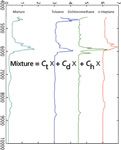
Figure 5: Absorbance spectra of pure dichloromethane, n-heptane, and toluene, and of a ternary mixture of the three (x-scale in wavenumbers), along with the concentration information that makes this the graphical representation of equation 3.
Mixture 1: toluene = 50%, dichloromethane = 25%, n-heptane = 25%
Mixture 2: toluene = 25%, dichloromethane = 50%, n-heptane = 25%
Note how, even though the amount of n-heptane is the same in both mixtures, the spectra are different because of the differences in concentrations of the other two components. Obviously, for the purpose of demonstration and pedagogical effect, we have exaggerated the spectra differences by choosing example mixtures in which the concentration differences are large. In "real" samples, with smaller composition differences between samples, the spectral changes are generally smaller and more subtle, nevertheless, the same effects occur, and indeed, form the basis for all quantitative spectroscopic analysis.
So we see now that the spectrum of a mixture is not merely the sum of the spectra of the components of the mixture, it is a weighted sum, the weighting factors being the concentrations of the individual components. What we need to do is to find a way to extract, from the spectrum of a mixture, the weighting factors that represent the contribution of each component to the final spectrum, because these weighting factors represent the concentrations of the components. If we call the weighting factors c1, c2, and c3, then the absorbance of the mixture at any wavelength will equal the sum of the weighted absorbances of the components of the mixture:

Extending this to the sums of the spectra, we rewrite equation 23 to reflect the spectra of the three components

where [M], [D], [T], and [H] represent the spectra (which are now vectors, in this representation) of the mixture, dichloromethane, toluene, and n-heptane, respectively, and the corresponding c1, c2, and c3 represent the concentrations of dichloromethane, toluene, and n-heptane, also respectively. We may find it convenient at various points to change the subscripts on the concentration terms to cD, cT, and cH to help us keep track of the different terms. We present this future change of terminology now, to help avoid future confusion.
Equivalence of Spectra and Numbers
Along the way, we also need to learn how to modify our point of view, as digitized spectra that appear be graphical constructs are in fact composed of numbers. Those numbers representing the spectral value (whether transmittance, absorbance, or whatever mode of spectral presentation is used.)
It is convenient to start with Figure 2b, which shows the spectra of the three pure components, plus the spectrum of the mixture. We will transform this figure, using an extremely simple transformation. We will transform it by rotating it 90°. This transformed graph is shown in Figure 4. Clearly, the rotation of the graph has not changed or otherwise affected any of the underlying properties of the data that the graph represents, nor does it change the relationships between any of the spectra.
In Figure 5, we have taken Figure 4 and added some symbols to it. We can now compare Figure 5 to equation 24. In equation 24, we represented the spectra of each of the components of the mixture by a symbol ([D], [T], [H]), each representing the corresponding spectrum.
In Figure 5 we have effectively rewritten equation 24 by replacing the symbol representing each spectrum by the actual spectrum.
Figure 5 is where the spectroscopy meets the math.
Howard Mark serves on the Editorial Advisory Board of Spectroscopy and runs a consulting service, Mark Electronics (Suffern, NY). He can be reached via e-mail: hlmark@prodigy.net
Jerome Workman, Jr. serves on the Editorial Advisory Board of Spectroscopy and is currently working in the medical device industry using spectroscopy. His email address is: JWorkman04@gsb.columbia.edu
References
(1) H. Mark and J. Workman, Spectroscopy 25(5), 16–21 (2010).
(2) H. Mark and J. Workman, Spectroscopy 25(6), 20–25 (2010).
(3) H. Mark and J. Workman, Spectroscopy 13(11), 18–21 (1998).
(4) H. Mark and J. Workman, Chemometrics in Spectroscopy (Elsevier, Amsterdam and New York, 2007).
(5) A. Schuster, Phil. Mag. 5, 243 (1903).
(6) A. Schuster, J. Astrophys. 21, 1 (1905).
(7) P. Kubelka and F.Z. Munk, Techn. Phys. 12, 593 (1931).
(8) G. Kortum, Reflectance Spectroscopy: Principles, Methods, Applications, 1st ed. (Springer-Velag, New York, 1969).
(9) W.W. Wendlandt amd H.G. Hecht, Reflectance Spectroscopy (John WIley & Sons, New York, 1966).
(10) D.J. Dahm and K.D. Dahm, Interpreting Diffuse Reflectance and Diffuse Transmittance: A Theoretical Introduction to Absorption Spectroscopy of Scattering Materials, 1st ed. (IM Publications, West Sussex, UK, 2007).
(11) H. Mark and J. Workman, Spectroscopy 21(5), 34–38 (2006).
(12) H. Mark and J. Workman, Spectroscopy 21(6), 34–36 (2006).

From Classical Regression to AI and Beyond: The Chronicles of Calibration in Spectroscopy: Part I
February 14th 2025This “Chemometrics in Spectroscopy” column traces the historical and technical development of these methods, emphasizing their application in calibrating spectrophotometers for predicting measured sample chemical or physical properties—particularly in near-infrared (NIR), infrared (IR), Raman, and atomic spectroscopy—and explores how AI and deep learning are reshaping the spectroscopic landscape.