Emerging Technology Trends in Atomic Spectroscopy Are Solving Real-World Application Problems
A look at ICP–MS, ICP–OES, X-ray fluorescence spectroscopy, and laser-induced breakdown spectroscopy in the areas of research and development, marketing, application, and use of these techniques.
This article looks at recent developments in inductively coupled plasma–mass spectrometry (ICP–MS), microwave-induced plasma–optical emission spectrometry (MIP-OES), X-ray spectroscopy, and laser-induced breakdown spectroscopy (LIBS) by exemplifying the diverse range of sample types they are analyzing and the unique application problems they are being asked to solve.
Atomic spectroscopic techniques are commonly used to carry out elemental determinations in a wide range of sample matrices from sub-parts-per-trillion concentrations up to high percentage levels. Inductively coupled plasma–mass spectrometry (ICP-MS) is universally recognized as the most sensitive ultratrace multielement technique with detection limits in the low parts-per-trillion range for the majority of elements, whereas X-ray fluorescence (XRF) spectrometry has traditionally been the technique of choice for carrying out high precision analysis of samples with high parts-per-million or low percentage concentrations. However, there are many application areas that are less demanding and do not require such stringent analytical requirements as these two techniques. For example, inductively coupled plasma–optical emission spectrometry (ICP-OES) has similar sample throughput characteristics as ICP-MS, but depending on the analyte, its detection limits are approximately three orders of magnitude higher (worse). More recently, a microwave-induced plasma (MIP)-OES system has become commercially available that offers the throughput of ICP-OES, but is more aligned to flame atomic absorption (FAA) in its detection capability. Additionally, laser-induced breakdown spectroscopy (LIBS), a relatively new commercial technique, is showing a great deal of promise for the analysis of materials with challenging sampling requirements. However, until recently LIBS was struggling to demonstrate that it could differentiate itself from the other more mature solid-sampling techniques like XRF or arc/spark emission.
The strength and weakness of any analytical technique are based on its ability to successfully address real-world application segments. With that in mind, let's take a more detailed look at some of these techniques by exemplifying the diverse range of sample types they are analyzing, with particular emphasis on the unique application problems they are being asked to solve.
Inductively Coupled Plasma–Mass Spectrometry
Even 31 years after the commercialization of ICP-MS, the flexibility of the technique is still one of its greatest attributes. Not only is it being used to carry out routine, high-throughput multielement analysis, but it is also ideally suited for more demanding applications such as ultratrace element speciation studies coupled with high performance liquid chromatography (HPLC). Every year, as more and more laboratories invest in the technique, the list of applications is becoming larger, extremely diverse, and, in some cases, more challenging. There have been many creative ways to address the difficult nature of complex sample matrices including the use of high-resolution, double focusing magnetic sector technology, automated sample introduction, and pretreatment techniques to preconcentrate the analytes of interest and remove the matrix before it enters the mass spectrometer. Recent developments have also seen the use of aerosol dilution sampling accessories to minimize the impact of the matrix on the interface cones and to reduce the solvent loading on the plasma to analyze samples with higher dissolved solids.
However, in my opinion, the most significant breakthrough in quadrupole-based ICP-MS has been the use of collision–reaction cells and interfaces to minimize, and, in some cases, totally remove problematic polyatomic spectral interferences created by the combination of ions from the matrix or solvent with ions from the argon plasma. The fact that a user now has the choice of either using a collision/reaction interface, a multipole-based collision cell with kinetic energy discrimination (KED), a low-mass cut-off design, or a true reaction cell with bandpass filtering, makes the technology a very powerful method development tool. This approach has been further refined by the commercialization of the triple-quadrupole ICP-MS system, in which one quadrupole is used as a mass filter or ion guide before the collision cell (actually an octapole and not a quadrupole) and a second analyzer quadrupole is placed after the collision cell, tuned to the analytes of interest. These advancements have opened up the technique to a multitude of new application areas for quadrupole-based ICP-MS, and, in many cases, is a viable alternative to magnetic-sector technology for spectrally complex samples. Some of these application areas include the direct analysis of seawater samples (1), the determination of trace metals in power plant flue gas desulfurization waters (FGDW) (2), the measurement of ultratrace levels of metals in human biological samples (3), and the analysis of pharmaceutical and nutraceutical materials according to the new United States Pharmacopeia (USP) Chapters 232, 233, and 2232 (4).
However, there is one application area that is proving to be particularly challenging, not because it's difficult to introduce the sample into the ICP-MS system or handle problematic interferences, but because it involves the optimization of the measurement protocol to enable the measurement of metallic nanoparticles at environmentally significant levels. The identification and characterization of extremely small nanoparticles in soils and groundwaters using ICP-MS is a rapidly emerging application that is in the process of being fine-tuned and refined by early researchers and is expected to be ready for routine use in the near future. Let's take a closer look at this challenging application.
Characterization of Engineered Nanoparticles
The use and benefits of engineered nanomaterials will not be discussed in this article because there is a great deal written about them in the public domain (5,6). However, the unique properties of engineered nanomaterials have also created intense interest about the environmental behavior of these materials. Because of the increased use of nanotechnology-based products, nanoparticles are more likely to enter the environment. Different engineered nanoparticles will have different properties and, therefore, will behave very differently when they enter the environment. So, to ensure the continued development of nanotechnology products, there is clearly a need to evaluate the risks posed by these engineered nanoparticles, which will require proper tools to carry out exposure assessment studies to better understand how they interact with soil, sediment, and water systems.
Current analytical approaches to assess the impact of nanoparticles on the environment include a combination of computer modeling to predict life cycles and direct analytical measurement techniques. Prediction of environmental concentrations of engineered nanoparticles through modeling is based on knowledge of how they are emitted into the environment, together with their eventual fate and behavior, which requires validation through the measurement of actual environmental concentrations. For engineered nanoparticles that have only recently been introduced into the environment, extremely sensitive methods are required. Although the direct measurement approach is not hampered by the underlying assumptions of exposure modeling, it is very important to ensure that direct observations are representative in time and space for the regional setting in which the observation was made.
Many analytical techniques are available for nanometrology, only some of which can be successfully applied to environmental health and safety of nanotechnology (nano-EHS) studies. Traditional methods for assessing particle concentration and particle size distributions include electron microscopy, chromatography, field-flow fractionation (FFF), centrifugation, laser light scattering, ultrafiltration, and UV spectroscopy. Difficulties generally arise because of a lack of sensitivity for characterizing and quantifying particles at environmentally relevant concentrations (low micrograms per liter). Furthermore, the lack of specificity of these techniques is problematic for complex environmental matrices that may contain natural nanoparticles with polydisperse particle distributions as well as heterogeneous compositions.
The Role of ICP-MS
Because of its multielement capability and extremely low detection limits, ICP-MS is ideally suited to the characterization of engineered nanoparticles that contain elements such as Ag, Au, Ti, and Fe, which have been integrated into larger products such as consumer goods, foods, pesticides, pharmaceuticals, and personal care products. The ubiquitous use of goods containing these nanomaterials will inevitably lead to environmental releases, which may be studied and quantified using state-of-the-art ICP-MS technology. Current areas of research include the coupling of ICP-MS with FFF, producing a powerful tool for sizing and separating engineered nanoparticles with extremely high sensitivity and selectivity. Recently, a great deal has been published about the benefits of this hyphenated multielement technique, so it will not be discussed in this article (7). Another very exciting area of research is single-particle ICP-MS, which is a novel technique for detecting and sizing metallic nanoparticles at environmentally relevant concentrations (8). Although this method is still in the development stage, it has shown a great deal of promise in several applications, including determining concentrations of silver nanoparticles in complex matrices such as wastewater effluent. The method involves introducing nanoparticle-containing samples, at very dilute concentration, into an ICP-MS system and collecting time-resolved data. Because of the dilution factor, very high sensitivity and short integration times are necessary to ensure the detection of individual particles as pulses of ions after they are ionized by the plasma. The observed pulse number is related to the nanoparticle concentration by the nebulization efficiency and the total number of nanoparticles in the sample, whereas the mass and, thus, the size of the nanoparticle is related to the pulse intensity. The principles of characterizing nanoparticles using single-particle ICP-MS are shown in Figure 1.
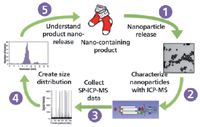
Figure 1: Principles of characterizing nanoparticles using single-particle ICP-MS analysis. (Figure courtesy of Colorado School of Mines.)
In this example, nano-Ag imbedded in athletic socks, which is used as a bactericide, has been shown to release during simulated wash cycles (step 1). By collecting and analyzing a simple aqueous solution with the ICP-MS system (step 2), and collecting data using the single-particle ICP-MS technique (step 3) the size, concentration, and associated dissolved material can be quantified — all of which are important parameters in environmental and biological modeling. After the raw data is collected, the dissolved content is at low signal intensity, with nanoparticles creating pulses above this background where the height of the pulse relates to the mass of analyte and the number of pulses correlates to the concentration of nanoparticles in the samples. The size distribution of particles in the sample can be calculated using well-understood single-particle ICP-MS theory (step 4). A histogram of nanoparticle diameter versus the number of events (nanoparticle number) can then be created to visualize the nanoparticle distribution in the sample, in addition to calculating the concentration of both the nanoparticles and dissolved fractions of the nanoparticle released from the products (step 5). The theory of size distribution will not be discussed here, but with this technique, scientists can have a better understanding of how nanomaterials will behave in the environment at realistic concentrations.
Optimized Measurement Protocol
However, for this approach to work effectively at low concentrations, the speed of data acquisition and the response time of the ICP-MS detector must be fast enough to capture the time-resolved nanoparticle pulses, which typically last less than 1 ms. If the electronics are not fast enough, two or three pulses can easily pass through and be erroneously detected as a single pulse. Figure 2 shows a real-world example of the time-resolved ICP-MS analysis of a mixture of 30-nm and 60-nm gold particles together with 5 ppb gold in solution (9).

Figure 2: Time-resolved analysis of 30-nm and 60-nm gold particles by single-particle ICP-MS. Adapted from reference 9.
Each peak represents the instrumental response for each integration point. If one of these time-resolved peaks is examined closely, as shown in Figure 3, it can be seen that the gold nanoparticle has been generated in <1 ms, showing the need for a very fast data acquisition rate, using short dwell and settling times for this kind of work. Ideally, for the measurement of nanoparticles, the ICP-MS system should be capable of using dwell times of 100 μs or less so the pulse can be fully characterized. Additionally, for single-element studies, some instruments offer a modification to the measurement protocol to run with no settling time to ensure that the maximum number of nanoparticle pulses is detected during the rapid transient event. However, if this capability is not an option, very short settling times on the order of 50 μs are required.
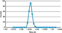
Figure 3: Time-resolved analysis of a gold nanoparticle using single-particle ICP-MS measurement protocol showing the pulse is fully characterized in less than 1 ms. Adapted from reference 9.
It should be emphasized that for normal multielement studies, a quadrupole–detector settling time is absolutely critical when scanning between masses to ensure the peak is identified and measured. But for single-element nanoparticle studies, it is more desirable if the quadrupole scans to the mass of interest, and sits on the peak taking data for the desired dwell time, without having to settle every time it takes a reading. For this type of work, a settling time actually degrades the quality of the data, because multiple nanoparticle pulses can easily be missed during this critical time and be mistaken for a single pulse. For this reason, the ability to run with no settling time is very beneficial for the characterization and detection of single-element nanoparticles by single-particle ICP-MS.
Microwave-Induced Plasma–Optical Emission Spectroscopy
ICP-OES has become the dominant technique for carrying out the multielement analysis of samples that require high-parts-per-billion and low-parts-per-million analyte levels. It was first developed for commercial use in the late 1970s as a response to a demand from the application community that FAA was limited in its ability to determine a large suite of elements in a timely manner. Initially available as a simultaneous spectrometer and then in the more flexible sequential configuration, ICP-OES rapidly became the technique of choice for laboratories where high sample throughput, multielement analysis was the overriding requirement. There was still a place for FAA in laboratories where the sample workload was significantly lower, but there still appeared to be applications where either the analyte or sample throughput requirements were too high for FAA or they were not high enough to justify the cost of an ICP-OES. Instrument vendors attempted to fill those gaps with either high cost, fully automated atomic absorption (AA) systems or low-cost ICP-OES systems, but each approach tended to be a compromise.
Today, it looks like this gap in the application toolbox has been filled with the recent development and commercialization of an MIP-OES system. Microwave-generated plasmas have been used as gas chromatography (GC) detectors for decades and were explored as potential excitation sources for emission studies back in the 1970s, when ICP was being investigated. However, it was found they had limited applicability because they were not considered robust enough for introducing liquids. As a result of this limitation in MIP technology, ICP became the dominant excitation source. To better understand this early limitation, let's take a closer look at how a microwave-induced plasma is generated.
A microwave-induced plasma basically consists of a quartz tube surrounded by a microwave waveguide or cavity. Microwaves produced from a magnetron fill the cavity and cause the electrons in the plasma support gas to oscillate. The oscillating electrons collide with other atoms in the flowing gas to create and maintain a high-temperature plasma. As in the inductively coupled plasmas, a high voltage spark is needed to create the initial electrons to create the plasma, which achieves a temperature of approximately 5000 K.
The limiting factor to their use was that with the low power and high frequency of the MIP, it was very difficult to maintain the stability of the plasma when aspirating liquid samples containing high levels of dissolved solids. Various attempts had been made over the years to couple desolvation techniques to the microwave-induced plasma, but they only managed to achieve limited success (10). However, the latest MIP technology (MP-AES, Agilent Technologies) appears to have overcome many of the limitations of the earlier designs. Before we go on to look at this recent commercial development and its applications areas, let's take a closer look its fundamental principles.
At the heart of this technology is a 2.5-GHz magnetron coupled into a nitrogen plasma, which is created using compressed air and a nitrogen generator. By using the magnetic field rather than the electric field for excitation, an extremely robust plasma is formed that is capable of handling much higher dissolved solids than previous MIP designs. The microwave waveguide concentrates both the axial magnetic and radial electrical fields around the torch, which creates a conventional-looking plasma, allowing for a traditional inert concentric nebulizer and double-pass spray chamber to be connected to the torch.
The optical system uses an axial viewing configuration, where the emission from the plasma is directed into a fast-scanning, 600-mm focal length, Czerny-Turner monochromator with a wavelength range of 178–780 nm. The system's 2400-lines/mm holographic grating, blazed at 250 nm for optimum UV performance, offers a resolution of 0.050 nm. The detection system is a back-lit charge-coupled device (CCD) array detector. The detector is cooled to 0 °C using a thermoelectric Peltier device and collects the analyte wavelengths and surrounding background spectra, allowing for simultaneous background correction.
Design Benefits
One of the biggest advantages of this particular design over ICP-OES is that it runs on compressed air, which means that no gaseous or liquid argon is required. This makes it very attractive for laboratories that are on a tight consumables budget. However, the benefits compared to FAA are probably where this technique will receive the most attention (11). These benefits include
- lower detection limits
- a wider linear dynamic range, which means larger concentration ranges can be determined
- increased sample throughput
- higher productivity, as it can be run unattended overnight
- no requirement to purchase or replace multiple hollow cathode lamps
- the ability to add other analytes to the suite of elements whenever the demand arises
- no safety concerns because neither acetylene nor nitrous oxide is required
Typical Applications
There is no question, based on the application material in the public domain that the MIP-OES system has been designed to fill the gap between FAA and ICP-OES, and particularly to address the many limitations of AA. Some of the applications that are being highlighted include the analysis of geological materials (12), particularly if there is a requirement for remote sampling or when field studies are being carried out; the analysis of petrochemical samples using the addition of air to reduce carbon buildup on the torch; analysis of major, minor, and trace elements in rice (13); and nonregulated applications, such as the environmental monitoring of industrial waste streams. However, the analysis of fruit juices and agricultural samples appears to be one of the most demanding FAA applications that can be readily addressed by using the new MIP-OES system (14). Now, let's take a closer look at this application.
The Determination of Major Elements in Fruit Juices
Major elements such as calcium, magnesium, sodium, and potassium are essential nutrients in most foodstuffs and, as a result, the routine monitoring of these elements is a common quality control requirement. FAA has been ideally suited to this application because it delivers the required performance at a cost-effective price. However, there are several analytical challenges when using FAA for this application that can be overcome by using MIP-OES. For example, the nitrogen-based plasma source operates at a much higher temperature than a flame, thus avoiding the chemical interferences associated with FAA. This eliminates the time consuming, element-specific sample preparation steps, gas condition changes, and burner head configurations required to analyze Ca, Na, K, and Mg in the same sample by FAA.
The plasma source in the new MIP-OES system also leads to improved performance with respect to detection limits and linear dynamic range when compared to FAA, which is important in an analysis where the elements can be present over a very wide range of concentrations. Additionally, the use of MIP-OES for this analysis also removes the need for matrix modifiers and ionization suppressants required by FAA. It's also worth mentioning that with no flammable gases required, the MIP-OES system is able to operate unattended (even overnight if required), if a laboratory has a very high workload.
Because the working range of the MIP-OES system exceeds FAA by up to 20×, only one dilution of the sample is required to measure the complete suite of elements. This is exemplified by the working concentration ranges of Ca, Mg, Na, and K, which are summarized in Table I.

Table I: The working concentration ranges of Ca, Mg, Na, and K by MIP-OES (14)
By simply diluting a fruit juice 20-fold in 5% HNO3, aspirating a sample into the instrument, and comparing the elements of interest with calibration standards made up in 5% HNO3, all the elements of interest can be quantified.
This is exemplified in Table II, which shows the analysis and percent recovery of Mg, Na, K, and Ca in certified reference apple and grapefruit juices.

Table II: The analysis and percent recovery of Mg, Na, K, and Ca in a certified reference apple and grapefruit juice by MIP-OES. (Note: Both fruit juices were certified by the Food and Environmental Food Agency, York, UK) (14).
X-ray Techniques
XRF, in both the wavelength-dispersive and energy-dispersive configurations, has traditionally been used for the determination of major and minor elemental concentrations in solid samples such as minerals, metals, polymers, cement, pharmaceuticals, and foodstuffs (15,16). Additionally, over the past couple decades, breakthroughs in miniaturization of optical components, electronics, and solid-state detectors have resulted in the commercialization of handheld devices to carry out measurements in the field that are difficult to perform in a laboratory because of sampling problems and, more recently, in the development of compact, on-line spectrometers for industrial process control applications (17,18). On the other hand, X-ray diffraction (XRD), which is typically used to get a better understanding of the crystalline structure of both man-made and natural materials, is better applied in a laboratory environment because the sample has to be in a suitable form to ensure the interaction of the X-rays with a uniformly flat surface. This is particularly true for mining or geological matrices, where the samples have to be ground to a fine homogeneous powder to be analyzed.
However, the future of X-ray analysis could be significantly different with a recent announcement from the Space Research Centre (SRC) at the University of Leicester in the UK, about a collaboration with an instrument vendor to develop a handheld mineral analyzer that requires no prior preparation of the sample. The analyzer is intended for the rapid mineral identification and quantification of ore-based mining samples in the field through a combination of XRD and XRF, and will be capable of directly analyzing the mineralogical components of a sample within a few minutes with no sample preparation — traditionally beyond the capabilities of conventional XRD equipment.
An X-ray Tool for the Characterization of Geological Samples with Minimal Sample Preparation
At the heart of this technology is back-reflection optical geometry, which enables a compact, lightweight XRD instrument design with no moving parts (19). In addition, the technique is combined with a complementary XRF spectrometer to provide information about the chemical elements in the sample. Besides the mining applications, it is also hoped that the technology will be used for remote or field-based studies including industrial applications such as geological surveying, precious metals prospecting, mining and quarrying, cement manufacture, soil analysis, and archaeological studies. In addition, it will be ideally suited for planetary studies, similar to the one being carried on the surface of Mars, thus avoiding the need for resource-intensive and technically challenging sample processing. Let's take a closer look at the fundamental principles of this exciting new breakthrough.
Fundamental Principles
The analysis of a powder by XRD methods is usually performed in an angle-dispersive mode, whereby an X-ray beam with a single wavelength is diffracted through a range of distinct scattering angles according to the Bragg equation. The dimensional spacings of the crystal are uniquely characteristic of each mineral phase, which are then used for identification, quantification, and structural analysis. An alternative configuration fixes the scattering angle and uses a broadband X-ray source, such as an X-ray tube. When used with an energy-resolving detector, this approach is known as energy-dispersive XRD (EDXRD). The novel technique described here applies EDXRD in a 180° back-reflection geometry as shown in Figure 4.
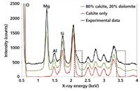
Figure 4: This novel EDXRD technique for the direct characterization of minerals uses a 180° back-reflection geometry configuration. Adapted from reference 19.
By ensuring a minimum distance between the sample and detector, only those photons that diffract at angles close to 180° are seen by the detector. Because each photon travels back along its incident path, the distance between the interaction point on the sample and the detector becomes irrelevant and doesn't matter if different parts of the sample lie at different distances to the detector. In fact, detailed analysis and ray-trace modeling shows that for an angular range limited to 160—180°, the technique is remarkably insensitive to sample morphology. This property is in complete contrast to conventional laboratory XRD techniques, which require a sample crushed to a fine powder, presented to the instrument with a uniformly flat surface and with sub-millimeter position accuracy.
Mineral Exploration Applications
One of the most exciting areas for this technology is determining the mineralogical composition of a metallic ore. The ability of the back-reflection XRD method to analyze unprepared whole rock specimens or other samples of nonuniform shape and size opens up new possibilities for in situ geological field investigations and on-line industrial quality and process control. There is currently a commercially available, portable XRD instrument (20) that was developed from NASA's Chemistry and Mineralogy (CheMin) instrument currently being used by the Curiosity Rover on the surface of Mars. However, this field device requires some degree of sample preparation by the user. On the other hand, the portable or handheld instrument based on the back-reflection XRD method described here would require a simple brushing the surface of a rock specimen before analysis. This design opens up enormous possibilities for geological investigations here on earth and on other planets. The major benefit of this technology over current instrumentation being used on Mars is that there would be no need for a rover vehicle to have its own sample handling system for grabbing, preparing, and delivering the sample to the instrument. With the back-reflected XRD system mounted on a rover sampling arm, it could be the primary instrument for directly determining the composition of surface rocks and soils.
To assess the applicability of this approach, a proof-of-concept experiment was carried out to demonstrate its feasibility. This is exemplified in Figure 5, which shows the spectral data of a pressed-powder pellet of quartz, mounted at two different arbitrary distances from the detector, and also tilted by 45°. The high degree of consistency between the three spectra demonstrates the irrelevance to sample distance and orientation, except for an overall intensity factor. The peaks labeled Si and O are caused by fluorescence, while all the other remaining peaks are caused by diffraction, except for those labeled 55Fe, which arise from the inadvertent exposure of a calibration source.
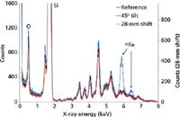
Figure 5: An XRD spectral display of a pressed-powder pellet of quartz, mounted at two different arbitrary distances from the detector, and also tilted by 45°. Adapted from reference 20.
To demonstrate the feasibility of the analysis of a whole rock specimen, a limestone was chosen because of its simple mineralogy. In Figure 6 the spectrum of the limestone experimental data is compared to the results of two model simulations, which are a pure calcite (CaCO3) and an 80:20 mixture of calcite and dolomite, (CaMg[CO3]2). The O-, Mg-, Al-, and Si-labeled peaks are caused by fluorescence from the corresponding elements, but the regions highlighted by the dotted boxes demonstrate the detection of dolomite as the secondary mineral in this sample (21).

Figure 6: The XRD spectrum of a limestone sample (experimental data) compared to the results of two model simulations, which are a pure calcite (CaCO3) and an 80/20% mixture of calcite and dolomite, (CaMg[CO3]2). Adapted from reference 20.
Laser-Induced Breakdown Spectroscopy
LIBS has been commercially available since the early 2000s, but only in the past 5 years has its application potential been fully explored. Initially developed by a group of government scientists in the early 1980s (22), it was first applied to the analysis of soils and hazardous waste sites because of its remote sampling capabilities (23). However, since it has been in the hands of the routine analytical community, it is now being used to solve real-world application problems (24). Although the analytical capability, performance, and elemental range of LIBS compares quite favorably with other AS techniques, it should not be considered a direct competitor to either ICP-OES or XRF. In my opinion, the unique benefits of LIBS are in its ability to sample a very diverse range of matrices, both in a laboratory environment and at remote locations out in the field. Let's take a closer look at the fundamental principles and capabilities of LIBS to get a better understanding of where it fits into the atomic spectroscopy toolbox.
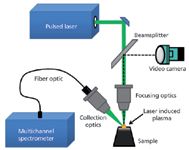
Figure 7: Optical configuration of a LIBS system. (Courtesy of TSI Inc.)
LIBS Fundamental Principles
LIBS is an atomic emission spectroscopic technique that uses a small plasma generated by a focused pulsed laser beam (typically from a Nd:YAG laser) as the emission source. The plasma formed is about 10× hotter than an inductively coupled plasma and as a result will vaporize just about any material it comes in contact with. The energy from the plasma excites the vaporized sample, which results in a characteristic emission spectrum of the elements present in the sample, which is then optically dispersed and detected by optical components traditionally used in an emission spectrometer (24). A typical optical layout of a LIBS system is shown in Figure 7. Figure 8 exemplifies a generated emission spectrum.
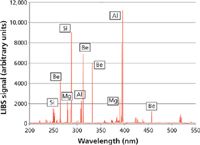
Figure 8: A typical LIBS emission spectrum. (Courtesy of TSI Inc.)
LIBS Capabilities
This has given LIBS some unique characteristics compared to other atomic spectroscopy techniques:
- Any type of solid, liquid, or gaseous sample can be vaporized and excited. It is not limited to liquids like ICP-OES or conducting solids like arc/spark emission.
- Unlike XRF, the majority of the periodic table is available, even the lighter elements like B and Li.
- The laser-induced plasma is readily generated in the open atmosphere negating the need for large argon flows or expensive consumables used in ICP instrumentation.
- The laser beam can be directed almost anywhere by the appropriate optical components or through a fiber optic, making it suitable for remote sampling applications such as hazardous waste sites or studies on other planets.
- The optical design makes it ideally suited to be put into a briefcase that can be carried around for field applications.
- Precise control of spot size and laser penetration allows surface mapping and depth profiling studies.
LIBS Application Areas
Some of the many applications that are being carried out today, which have contributed to the growing popularity of LIBS include
- the determination of major and minor elements in metallurgical samples
- identification and classification of different materials using multivariate processing techniques
- microanalysis of gemstones and precious minerals
- trace element analysis of glass and quartz materials
- minimally destructive analysis of forensic samples
- uniformity of pharmaceutical ingredients
- analysis of tablet coatings
- direct analysis of coals
- measurement of the metallic content of liquid baths or flowing process streams
- remote field sampling of environmental and geological materials
There is no question that the most high-profile LIBS system is the ChemCam instrument onboard NASA's Curiosity Rover, which landed on the surface of Mars in the fall of 2012. After the rock or mineral has been prepared for analysis by Curiosity's robotic arm, the ChemCam system can analyze the sample remotely from a distance of up to 20 ft away, by firing the laser pulses and directing the resulting emission from the generated plasma back to the on-board spectrometer via fiber optics for detection and quantitation (26). This work will be extremely relevant to better understand the geological composition of Mars and ultimately how our solar system came into existence (27).
Characterization of Gemstones and Precious Minerals
One of the most intriguing application areas for LIBS has been sourcing the geographical origin of commercially valuable minerals (28). Some of these materials are gemstones, and others are referred to as "conflict minerals," which when refined are used to make critical components for consumer electronic products. Profits from the mining of these minerals have been used to fund armed rebels and militia groups fighting civil wars, which have resulted in deaths and human rights violations of millions of people in the Democratic Republic of the Congo in Central Africa. In compliance with the 2010 Wall Street Reform and Consumer Protection Act, the US government has attempted to stop conflict minerals from getting into circulation by proposing a new set of rules that require manufacturers of electronic equipment to disclose whether specific minerals have originated from this region (29).
This geochemically complex problem has traditionally been beyond the capability of conventional analytical techniques that use binary or ternary provenance plots for proof of origin. By using LIBS and collecting multiple spectra of major, minor, and trace elements over a defined wavelength range, analysts can obtain a fingerprint of the composition of a complex geological mineral to identify its source. This was demonstrated in a 2012 pilot study by a group of researchers who investigated 10 different minerals, consisting of more than 3000 samples (30). They looked at LIBS spectra consisting of more than 40,000 wavelengths between 200 nm and 1000 nm to create a statistically valid sample set, which was then used to build a database for each mineral investigated. To enhance the proof of concept, multiple points on each mineral were investigated to generate approximately two million data points per sample, which translated into almost 70 million data points per geographical location. Cross-validation of the LIBS data sample set using advanced statistical pattern recognition and chemometric methods compared the signatures of completely unknown samples to a large database of signatures of extremely well-documented specimens. The software correctly identified the geographical source of 98% of the minerals studied, as can be seen by the data for the gemstones in Table III and the conflict minerals in Table IV.

Table III: Identification of the geographical origin of gemstones using LIBS (29)
This on-going investigation has collected and analyzed more than 40,000 specimens to date, representing 225 unique locations in 40 countries covering six continents. It has shown that the use of LIBS, together with powerful pattern recognition software is ideally suited to identify and track the source of gemstones and minerals. Additionally, the ease of operation and portability of LIBS eliminates the need to analyze samples in the laboratory, thus allowing the rapid identification at strategic locations in the field.

Table IV: Identification of the geographical origin of conflict minerals using LIBS (29)
Final Thoughts
It was not the goal of this article to give an exhaustive summary of every sample type being analyzed by atomic spectroscopy techniques, but rather to provide a snapshot of some of the more novel application areas that are emerging into the real world. In particular, I wanted to take a look at some of the more recent instrumental developments to see how they compare with the more traditional techniques. I chose ICP-MS because it continues to be the most powerful ultratrace technique and MIP-OES because it represents a refreshing alternative to conventional atomic spectroscopy instrumentation, which appears to fit in quite nicely between FAA and ICP-OES. On the other hand, I believe the capabilities of X-ray spectrometry will most definitely be enhanced by the development of new handheld XRD and XRF systems for mineral exploration. Finally, LIBS is showing that it offers unique benefits, especially when the sample or the sampling requirements are too demanding for other solid sampling techniques.
References
(1) S. McSheehy-Ducos, Spectroscopy: Applications of ICP & ICP-MS Techniques for Today's Spectroscopists supplement, 26(11), 22 (2011).
(2) R. Burrows, S. Wilbur, and R. Clinkscales, Spectroscopy 26(11), 30–35 (2011).
(3) M. Hamester, R. Chemnitzer, P. E. Riss, A. Gaal, X. D. Wang, and R. Thomas, Spectroscopy 27(7), 20–27 (2012).
(4) L. Davidowski, A. Shultz, K. Uhlmeyer, E. Pruszkowski, and R. Thomas, Spectroscopy: Applications of ICP & ICP-MS Techniques for Today's Spectroscopists supplement, 27(11), 8–17 (2012).
(5) National Nanotechnology Initiative: http://www.nano.gov/.
(6) Project on Emerging Nanotechnologies: http://www.nanotechproject.org/process/assets/files/6703/nano_researchbrief_em.pdf.
(7) D. Mitrano, J. Ranville, K. Neubauer, and R. Thomas, Spectroscopy 27(9), 36–44 (2012).
(8) D.M. Mitrano, E.K. Leshner, A. Bednar, J. Monserud, C. P. Higgins, and J.F. Ranville, Environ. Toxicol. Chem. 31(1), 115–121 (2012).
(9) C. Stephan, "Paper M05, Nanomaterials Analysis and Characterization," presented at the Winter Conference on Plasma Spectrochemistry, Amelia Island, Florida, 2014.
(10) K. Jankowski, J. Anal. At. Spectrom. 14, 1419–1423 (1999).
(11) Agilent Technologies Application Note, http://www.chem.agilent.com/Library/technicaloverviews/Entitled%20Partner/5991-3807EN.pdf.
(12) Agilent Technologies Application Note: http://www.chem.agilent.com/Library/applications/5991-3772EN.pdf.
(13) Agilent Technologies Application Note, http://www.chem.agilent.com/Library/applications/5991-3777EN.pdf.
(14) Agilent Technologies Application Note, http://www.chem.agilent.com/Library/applications/5991-3613EN.pdf.
(15) R. Yellepeddi and R. Thomas, Spectroscopy 21(9), 36–41 (2006).
(16) J. Martin, L. Anderson-Smith, G. Adjei-Bekoe, and R. Thomas, Spectroscopy 25(4),40 (2010).
(17) Rigaku Applied Technologies Application Note #1306, http://www.rigaku.com/press/nexol/1306.
(18) Rigaku Applied Technologies Application Note #1336, http://www.rigaku.com/products/process/nexol/app1336.
(19) G.M. Hansford, J. Appl. Crystallogr. 44, 514–525 (2011).
(20) Olympus BTX Benchtop XRD System Application Notes, Olympus website: http://www.olympus-ims.com/en/xrf-xrd/mobile-benchtop-xrd/btx/.
(21) G.M.Hansford, Nucl. Instrum. Methods Phys. Res., Sect. A 728, 102–106 (2013).
(22) L.J. Radziemski, D.A. Cremers, and T.R. Loree, Spectrochim. Acta, Part B 38(12), 349–355 (1983).
(23) K.Y. Yamamoto, D.A. Cremers, M.J. Ferris, and L.E. Foster, Appl. Spectrosc. 50(2), 222–233 (1996).
(24) R.S. Harmon, R.E. Russo, and R.R. Hark, Spectrochim. Acta, Part B 87, 11–26 (2013).
(25) D. Cremers and L. Radziemski, Handbook of Laser Induced Breakdown Spectroscopy (John Wiley & Sons, Ltd., Hoboken, New Jersey, 2006).
(26) NASA's Mars Science Laboratory website: http://mars.nasa.gov/msl/mission/instruments/spectrometers/chemcam/.
(27) R.C. Weins and S. Maurice, Geochemical News, June (2011), http://www.geochemsoc.org/publications/geochemicalnews/gn145jun11/chemcaminstrumentsuit.
(28) R.S. Harmon, J.J. Remus, C. McManus, F.C. DeLucia, J. Gottfried, and A.W. Miziolek, Appl. Geochem. 24, 1125–1141 (2009).
(29) Conflict Minerals, Proposed Rule: Federal Register 75, 80948-80975, (December 23, 2010).
(30) C. McManus, T. Likes, J. Dowe, N. McMillan, K. Yetter, and S. Buckley, "Assessment of Provenance of Conflict Minerals using the Materialytics Sequencing System" presented at the Geological Society of America Annual Meeting, Minneapolis, Minnesota, 2011.
Robert Thomas is a consultant and science writer specializing in trace-element analysis. Direct correspondence to: robert.james.thomas@verizon.net
AI Shakes Up Spectroscopy as New Tools Reveal the Secret Life of Molecules
April 14th 2025A leading-edge review led by researchers at Oak Ridge National Laboratory and MIT explores how artificial intelligence is revolutionizing the study of molecular vibrations and phonon dynamics. From infrared and Raman spectroscopy to neutron and X-ray scattering, AI is transforming how scientists interpret vibrational spectra and predict material behaviors.
Trends in Infrared Spectroscopic Imaging
September 13th 2013An interview with Rohit Bhargava, winner of the 2013 Craver Award. This interview is part of the 2013 podcast series presented in collaboration with the Federation of Analytical Chemistry and Spectroscopy Societies (FACSS), in connection with SciX 2013, the federation?s North American conference.
Advancing Corrosion Resistance in Additively Manufactured Titanium Alloys Through Heat Treatment
April 7th 2025Researchers have demonstrated that heat treatment significantly enhances the corrosion resistance of additively manufactured TC4 titanium alloy by transforming its microstructure, offering valuable insights for aerospace applications.