Pump–Probe Microscopy: Theory, Instrumentation, and Applications
Spectroscopy
Excited state dynamics provides an intrinsic molecular contrast of samples examined. These dynamics can be monitored by pump probe spectroscopy which measures the change in transmission of a probe beam induced by a pump beam. With superior detection sensitivity, chemical specificity and spatial-temporal resolution, pump probe microscopy is an emerging tool for functional imaging of non-fluorescent chromophores and nanomaterials. This article reviews the basic principle, instrumentation strategy, data analysis methods, and applications of pump probe microscopy. A brief outlook is provided.
Excited-state dynamics provides an intrinsic molecular contrast of samples examined. These dynamics can be monitored by pump–probe spectroscopy, which measures the change in transmission of a probe beam induced by a pump beam. With superior detection sensitivity, chemical specificity, and spatial–temporal resolution, pump–probe microscopy is an emerging tool for functional imaging of nonfluorescent chromophores and nanomaterials. This article reviews the basic principles, instrumentation strategy, data analysis methods, and applications of pump–probe microscopy. A brief outlook is provided.
As a pioneer of femtochemistry, Nobel laureate Ahmed Hassan Zewail (1–3) recorded the snapshots of chemical reactions with sub-angstrom resolution through an ultrafast femtosecond transient absorption (TA) technique. In a transient absorption experiment, a laser pulse pumps a molecule into an excited state. The excited state itself exhibits relaxation dynamics on the femtosecond or picosecond timescale. A second laser pulse then probes the population in the excited state at different temporal delays with respect to the excitation. This analysis method reveals the dynamics of the excited state and is termed as pump–probe spectroscopy.
Pump–probe microscopy, also known as transient absorption microscopy, is an emerging nonlinear optical imaging technique that probes the excited state dynamics, which is related to the third-order nonlinearity (3,4). Pump–probe microscopy is an attractive spectroscopic imaging technique with the following advantages: First, it is nondestructive to cells and tissues and can be performed without tissue removal (5). Thus, it can be used as a repeatable diagnostic tool. Second, it is a label-free technique and doesn’t need an exogenous target (4). Third, as a nonlinear optical technique, pump–probe microscopy can image endogenous pigments with three dimensional (3-D) spatial resolution (6). Fourth, unlike linear absorption, which suffers from scattering in a tissue sample, the pump–probe technique only measures absorption at the focal plane, which offers optical sectioning capability (6). Fifth, compared to scattering measurements, this absorption-based method has a weaker dependence on the particle and thus is highly sensitive to nanoscale subjects (8–11). Sixth, pump–probe microscopy with near-infrared laser pulses permits biological applications with an enhanced penetration depth and a lower level of tissue damage (12).
In 1990s, Dong and coworkers used pump–probe microscopy to measure fluorescence lifetime (13). In 2007, the Warren group reported pump–probe imaging with a high-frequency modulation scheme (14). Their work demonstrated the feasibility of imaging melanin by using two-color two-photon absorption (TPA) or excited state absorption (ESA) processes. Since then, extensive research has been conducted by harnessing the merits of pump–probe microscopy. A majority of the research focused on nonfluorescent chromophores such as hemoglobin and cytochromes, which absorb light but do not emit fluorescence efficiently (15). Fu and colleagues used two-color absorption to measure the degree of oxygenation based on the different decay constants of deoxyhemoglobin and oxyhemoglobin (16). Pump–probe microscopy can efficiently discern hemoglobin and melanin, the two major absorbers in a biological tissue. Based on their signatures from the time-resolved curves, hemoglobin shows a purely positive response because of excited state absorption, whereas melanin (eumelanin and pheomelanin) demonstrate a negative (ground state bleaching) signal when the pump beam and probe beam spatially and temporally overlap (5). In addition, pump–probe microscopy enables the discrimination of melanomas by determining the ratio between eumelanin and pheomelanin. Melanin play an important role in skin and hair pigmentation and melanomas (17). Without external staining, pump–probe imaging yielded novel insight into the differentiation of eumelanin and pheomelanin among thin biopsy slices and has been used to probe the metastatic potential of melanocytic cutaneous melanomas (16). Besides applications to pigments in biological tissue, pump–probe microscopy has also been applied to distinguish various kinds of pigments in arts based on their decay differences (18–21).
Another significant application of pump–probe microscopy is for characterization of single nanostructures including gold nanorods (22) and single-wall nanotubes (SWNTs) (23–26). Specifically, Jung and coworkers for the first time deployed the phase of the pump–probe signal as a contrast to distinguish semiconducting carbon nanotubes from metallic ones (25). Tong and colleagues further used this contrast for imaging semiconducting and metallic nanotubes in living cells (26). By tuning the excitation wavelength, which is resonant with the lowest electronic transition in SWNTs, Huang and colleagues exploited the band-edge relaxation dynamics in isolated and bundled SWNTs (23). Through assembling SWNTs with CdS, Robel and colleagues demonstrated the charge-transfer interaction between photoexcited CdS nanoparticles and SWNTs by transient absorption (24).
In this review, we summarize the contrast mechanisms and instrumentation strategies of pump–probe microscopy and highlight some of these significant applications. Because of space limitations, we could not cover the entire literature and would recommend to the readers other excellent articles in this field (27–32).
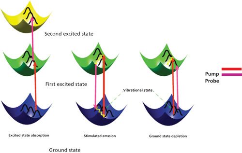
Figure 1: Three major processes in a pump–probe experiment: (a) Excited state absorption, (b) stimulated emission, and (c) ground-state depletion. For ground-state depletion, the number of the molecules in the ground state is decreased upon photoexcitation, consequently increasing the transmission of the probe pulse. For stimulated emission, photons in its excited state can be stimulated down to the ground state by an incident light field, thus leading to an increase of transmitted light intensity on the detector. In the case of excited-state absorption, the probe photons are absorbed by the excited molecules, promoting them to the higher energy levels.
Pump–Probe Theory
In a typical pump–probe measurement, the pump-induced intensity change of the probe is measured by a lock-in amplifier referenced to the modulated pump pulse. Then this change is normalized by the probe beam intensity to generate ΔIpr/Ipr (33). To express this process at molecular level, we define the absorption coefficient for an electronic transition between level “i” and level “j” as

where σij(ω) is the cross section from electronic state i to j, and Ni and Nj are the populations of the initial and final states, respectively. Conventionally, α is positive for absorption and negative for gain (33).
The pump pulse acts on the sample by changing the energy level population, N→N + ΔN. As a consequence, the population of excited states will increase at the expense of that of the ground state. Such change is measured by the probe beam:

where d is the sample thickness. The expression is derived from the Lambert-Beer relation within the small signal approximation. The “j” term describes all possible excited states (33).
Depending on the probe energy, three effects on the transmitted pulse can be observed: When the probe pulse is resonant with i→j transitions (i ≠ 0), then the probe pulse is absorbed by the molecule, reducing the transmission of the probe pulse. This negative ΔIpr/Ipr signal change is therefore called excited state absorption (ESA). When the probe pulse is resonant with 0→j transmission, the probe transmission is enhanced upon pump excitation. This positive ΔIpr/Ipr phenomenon is called ground-state depletion (GSD). When the lowest excited state is dipole-coupled to the ground state and the probe pulse is resonant with the transition, stimulated emission (SE) occurs. An increased transmission is observed in a SE process.
These three major processes are illustrated in Figure 1. A detailed description is provided in the following sections.
Excited-State Absorption
Excited-state absorption (ESA) is a process where the probe photons are attenuated by excited states as shown in Figure 1. Since the 1970s, picosecond laser-based ESA measurements have been extensively used to measure ground and excited-state dynamics (34,35). Compared to two-photon absorption, which goes through a virtual intermediate state, excited-state absorption significantly enhances the detection sensitivity by bringing a resonance with a real intermediate electronic state. The mechanism for this process (36) can be described using the following equation:

where N0 is the molecular concentration at ground state; σpr and σ′pr are the linear absorption cross sections of the ground state and excited states for the probe beam, respectively; νpu represents the pump frequency and τ is the lifetime of the excited state (assume this is a single-exponential decay); and Δt is the time delay between pump beam and probe beam. Ipu and Ipr denote the intensity of pump beam and probe beam, respectively. In the presence of a pump pulse, excited-state population would give birth to the transmission changes of the probe. Equation 3 demonstrates that only at Δt = 0 when the pump beam and probe beam are spatially and temporally overlaid can ΔIpr have the biggest value. As Δt becomes longer, ΔIpr depicts as an exponential decay curve convoluted with an instrumental response function that is a Gaussian function.
Stimulated Emission
When interrogating the short-lived excited states in pump–probe experiments, the photons in the excited states are stimulated down to the ground state by a time-delayed probe pulse as shown in Figure 1. This process is called stimulated emission (37). The absorption coefficient decreases with increasing excitation irradiance. The decrease in absorption happens due to the annihilation of the number densities of both the ground state and the state being excited, this process can be portrayed as equation 4:
From equation (4), we can tell at Δt = 0, strongest signal is achieved. As Δt becomes longer, the transmission change of probe also demonstrates an exponential decay curve convoluted with Gaussian function. Based on the stimulated emission, Min and colleagues achieved nanomolar detection sensitivity of nonfluorescent chromophores (37). The integrated intensity attenuation of the excitation beam can also be expressed as

where S ~ 10-9 cm2 denotes the beam waist, and σ01 ~ 10-16 cm2 represents the absorption cross section from ground state to the first electronic state. The stimulation beam will experience a transmission gain after interaction with the molecules:


From equation 7, we can conclude that the stimulated emission process shows overall quadratic power dependence, allowing three-dimensional optical sectioning. In addition, the linear dependence upon the concentration of analyte allows for quantitative analysis. The detected sensitivity would be down to 10-9 M if the incident irradiance of pump beam and probe beam are in the range of megawatt cm-2 (37).
Ground-State Depletion
Ground-state depletion (GSD) microscopy is a form of super-resolution light microscopy suggested almost a decade ago (38), and it was first demonstrated in 2007 (39). Similar to stimulated emission, it presents as an out-phase signal (Figure 1). The overall mechanism is consistent with other transient absorption mechanisms. If expressed in equation form, the GSD process has the same expression as stimulated emission in equation 4. The only difference lies in the probe wavelength. For GSD, the probe is chosen close to the maximal absorption peak, whereas the probe beam in the case of stimulated emission is selected away from the absorption peak.
Based on ground-state depletion, single-molecule detection at room temperature has been achieved (40). Under the condition that both pump and probe beams (continuous-wave lasers) were chosen close to near saturation intensity levels (350 μW at the focus for each beam), a shot noise limited sensitivity is achieved. The detected sensitivity for Atto647N is 15 nM with 1s integration time. The order of modulation depth of the transmitted probe beam by a single molecule (Atto647N) is ~10-7, which means we can still demodulate the signal from a lock-in amplifier. Based on the mechanism above, ground-state depletion microscopy could reach single-molecule detection (40). The ground state depletion method could also be applied to localize fluorescence emission from fluorophores bound to the surface of a nanowire, thus making it possible to map out the structure of a nanowire (41). Zink and colleagues also showed how GSD microscopy can be applied to measure tubulin modifications in epithelial cells (42). High sensitivity coupled with optical sectioning capability makes ground-state depletion microscopy an important emerging technique.
Instrumentation
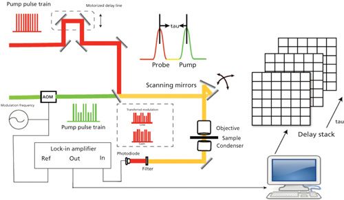
A typical pump–probe imaging setup is shown in Figure 2. An optical parametric oscillator pumped by a high-intensity mode-locked laser generates synchronous pump and probe pulse trains. The Ti:sapphire oscillator is split to separate pump and probe pulse trains. Temporal delay between the pump and probe pulses is achieved by guiding the pump beam through a computer-controlled delay line. Pump beam intensity is modulated with an acousto-optic modulator (AOM), and the intensity of both beams is adjusted through the combination of a half-wave plate and polarizer. Subsequently, pump and probe beams are collinearly guided into the microscope. After the interaction between the pump beam and the sample, the modulation is transferred to the unmodulated probe beam. Computer-controlled scanning galvo mirrors are used to scan the combined lasers in a raster scanning manner to create microscopic images. The transmitted light is collected by the oil condenser. Subsequently, the pump beam is spectrally filtered by an optical filter, and the transmitted probe intensity is detected by a photodiode. A phase-sensitive lock-in amplifier then demodulates the detected signal. Therefore, pump-induced transmission changes of the sample versus time delay can be measured from the focus plane. This change over time delay shows different decay signatures from different chemicals, thus offering the origin of the chemical contrast.
Figure 2: Schematic illustration of pump–probe microscopy.
Generally speaking, lasers applied in pump–probe microscopy can be divided into two types: systems working with relatively high pulse energy (5–100 nJ) and repetition rate of 1–5 kHz, and systems using a low pulse energy (0.5–10 nJ) and >1 MHz repetition rate (27). With appropriate detection schemes that involve multichannel detection on a shot-to-shot basis, the first type can achieve the signal detection sensitivity of ~10-5 units of absorbance over a broad wavelength range (27). Nevertheless, the presence of multiple excited states under high excitation density conditions leads to singlet-singlet annihilation (43). Therefore, this scheme is sensitive to artifacts. The second type with high repetition rates allows for averaging more laser shots per unit time. As a result, the detection sensitivity of ~10-6 units of absorbance can be achieved (28). By employing high-frequency (that is, megahertz) lock-in modulation, Hartland and coworkers detected signals from isolated single-walled carbon nanotubes with a sensitivity of ΔI/I ~ 5 × 10⁻⁷ (44). Moreover, in this scheme, the modulation provided by either an AOM or an electro-optic modulator (EOM) operates at a high frequency in the range of 100 kHz to 10 MHz, where the noise approaches the shot noise limit. One possible drawback of such setups is their high probability of detecting the accumulation of long-lived species, such as triplet or charge-separated states (27).
When it comes to the detection of pump–probe signal, a phase-sensitive lock-in amplifier is usually indispensably used to demodulate the probe signal. Slipchenko and colleagues reported a cost-effective tuned amplifier for frequency-selective amplification of the modulated signal. By choosing a pump beam of 830 nm and a probe beam of 1050 nm, the tuned amplifier can be used for pump–probe imaging of red blood cells. This lock-in free method improved the single-to-noise ratio by one order of magnitude compared to conventional detection based on a lock-in amplifier (45).
Spatial resolution is designated as the distance between two points of the sample that can be resolved individually according to the Rayleigh criteria. The lateral (r0) and axial (z0) resolutions are defined (46) as

where λ is the wavelength, n is the refractive index of the medium and NA is the numerical aperture. By using spatially controlled saturation of electronic absorption, diffraction limit in far-field imaging of nonfluorescent species could be broken as shown in Figure 3a. Wang and colleagues designed a doughnut-shaped laser beam to saturate the electronic transition in the periphery of the focal volume, thus introducing modulation only at the focal center. By raster scanning three collinearly aligned beams, high-speed subdiffraction-limited imaging of graphite nano-platelets was achieved (47).
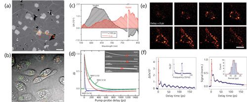
Figure 5: Imaging nanomaterials by pump–probe microscopy. (a) TA imaging of graphene on glass coverslip. 0 stands for defects, 1 is single layer graphene, 2 is double layer, 3 is triple layer, respectively. Pump = 665 nm (1.10 mW) and probe = 820 nm (0.68 mW), respectively. Data adapted from reference 70. (b) Transient absorption image of DNA-SWNTs internalized by CHO cells after 24 h incubation. Gray, transmission of cells; green, S-SWNTs; red, M-SWNTs. Pump = 707 nm, probe = 885 nm. The laser power post-objective was 1 mW for the pump beam and 1.6 mW for the probe beam. Adapted with permission from reference 26. (c) Decay-associated spectra of the triplet (red) and singlet (black) excitons of tetracene obtained by global analysis of the ensemble transient absorption spectra with the probe polarization to maximize triplet absorption. Data adapted from reference 75. (d) Pump–probe microscopy decay kinetics following photoexcitation of a localized region in three different Si nanowires; NW1 (red) and NW2 (green) are intrinsic, and NW3 (blue) is n-type. Curves are fit to a tri-exponential decay. Inset shows the SEM image of three wires. Adapted with permission from reference 76. (e) 3D transient absorption microscopic images of gold nanodiamonds in living cells taken from eight successive focal planes with 1-μm step. Scale bar: 20 µm. Data adapted from reference 77. (f) Transient absorption trace from a single Ag nanocube from a sample with an average edge length of 35.5 ± 3.4 nm (left). The inset shows the Fourier transform of the modulated portion of the data. Ensemble transient absorption trace for the Ag nanocube sample (right). Inset gives a histogram of the measured periods from the single-particle experiments, red line is the distribution calculated from the size distribution of the sample. Adapted with permission from reference 78.
Alternatively, Miyazak and colleagues (48) demonstrated the use of annular beams in pump–probe microscopy to improve spatial resolution in the focal plane, since the point spread function (PSF) in pump–probe microscopy is 23% (43%) smaller than the diffraction-limited spot size of the pump (probe) beam. The authors also used intensity modulated continuous wave laser diodes in a balanced detection scheme to achieve subdiffraction resolution with shot-noise limited sensitivity (49,50).
Regarding the sensitivity, single-molecule detection can be achieved through pump–probe microscopy. Chong and coworkers conducted ground-state depletion microscopy and achieved a detection limit of 15 nM with a 1-s integration time, which corresponds to 0.3 molecules in the probe volume, indicating the detection of a single-molecule absorption signal as shown in Figure 3b (40). In their work, the sample was illuminated by two tightly focused laser beams where the pump beam and the probe beam have different wavelengths but both are within the molecular absorption band of the analyzed sample. In this case, the pump beam only excites a molecule so that it only stays in its ground state, and, hence, photons from the probe beam can’t be absorbed. Fast on-off modulation of a strong, saturating pump beam leads to the modulation of transmitted probe beam at the same modulation frequency.
Data Analysis Methods
Generally, two methods can be used to analyze a decay curve. The easier method is multiexponential fitting to get the decay constants. However, a drawback is that its accuracy is relatively low. The other method is called phasor analysis, a method that needs neither any assumptions regarding the physical model nor integration fitting to determine the lifetimes of multiexponential signals (51–53). When dealing with a long lifetime (~1 ns), another method that is based on phase information and modulation frequency can be used as is discussed below.
Multiexponential Fitting
Multiexponential fitting, as the name implies, fits the time-resolved curves with an exponential decay model. This method is easy to conduct and understand. The time-resolved intensity is regarded as the conjugation between the instrumental response R(t) and the response from sample S(t):

Suppose the time resolution of the detector is modeled by a Gaussian function with a full width half maximum as σ:

In this case, pump–probe decay is modeled by an exponential decay with decay constant τ:

Then the convolution integral is

where erf (x) is the error function, a standard function in most mathematical software packages. For single exponential decay, the mathematical equation for the time-resolved decay curve is

where τ is the decay constant and I0 is the signal from background. A similar equation can be used for double exponential decay. After fitting with this model, we obtain the real decay constant τ along with the laser pulse width σ.
Through the deconvolution approach, we could resolve the time constant purely from decay of chemicals without the effect of laser response function. However, the drawback of this method is that it is sensitive to the initial input parameters, and therefore its accuracy is relatively low.
Phasor Analysis
Phasor analysis is a method that translates the time-resolved decay curve into a single point at a given frequency in the phasor space. One of the most advantageous features of phasor analysis when applied to fluorescent-lifetime imaging microscopy (FLIM) (52,53) is that it has the capability to quantitatively resolve a mixture of fluorophores with different lifetimes. Phasors from those mixtures display linearly across the phasor plot (54). For the first time, Fereidouni and colleagues proved spectral phasor analysis was powerful for the analysis of the fluorescence spectrum at each pixel (55,56). Fu and colleagues further applied this analysis method to hyperspectral stimulated Raman scattering data. It allows the fast and reliable cellular organelle segmentation of mammalian cells, without any a priori knowledge of their composition or basis spectra (57).The basic mechanism for this method is described through mapping the real parts of the signal against the imaginary parts of the signal after Fourier transform of the time-resolved curve:


Any multicomponent signal can be described as

where fi is the fraction of each independent species contributing to the total signal:

By plotting g(ω) against s(ω) at a given frequency, we can map the distribution of different chromophores with distinct lifetimes in the semicircle coordinate. Here ω is a free parameter depending on the separation efficiency. Robles and colleagues demonstrated its capability to discriminate eumelanin, pheomelanin, and ink by phasor analysis as shown in Figure 4 (54).
Figure 4: Phasor analysis to interrogate pump–probe signal. Experimental transient absorption spectra of hemoglobin (Hb), sepia eumelanin, syhthetic pheomelanin, and surgical ink (top left). Phasor difference of mixtures of eumelanin and pheomelanin (eumelanin fraction of 75%, 50% and 25%) along with their phasor locations on the s-g coordinate (top right). Cumulative histogram phasor plot of 17 ocular melanoma samples at frequency /2 THz (bottom left) and 1.4 THz (bottom right). Adapted with permission from reference 54.
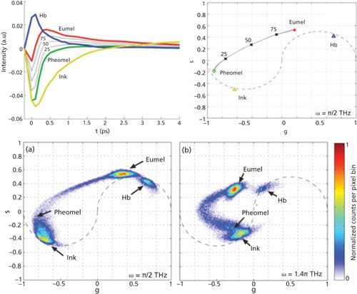
The phasor representation of lifetime images has become popular because it provides an intuitive graphical view of the fluorescence lifetime content without any prior knowledge. Meanwhile, it significantly improves the overall signal-to-noise ratio when used for global analysis. Besides that, the region of interest selected in the phasor plot can be mapped back to its corresponding image to realize segmentation (56).
Frequency Domain Approach
The frequency domain approach is more suitable for long-lived excited state. In this method, the lifetime information is extracted through a phase-sensitive detection. A simple model tan Ï = ω * τ is applied to calculate the lifetime on the basis of phase change corresponding to different modulation frequency. When a modulated pump beam I1(t) = I1(1+cos ωt) is incident on the sample, the excited state population is given by Miyazaki and colleagues (58) in the following equation:

Where


Here, σ1 is the absorption cross section, ν1is the frequency of the pump, h is the Planck constant, s is the beam waist area at the focal point, Ï is the phase calculated from the x and y channel signals, and τ is the excited-state lifetime. In the case of a long excited-state lifetime, equation 20 suggests an efficient method: tan Ï = ω * τ. This equation demonstrates the linear relationship between tan Ï and modulation frequency ω and the corresponding phase images. The slope of this equation yields the lifetime of the excited state. It is worth noting that because of the relatively larger shot noise at lower modulation frequency, the standard deviation is very high (59).
Applications of Pump–Probe Microscopy
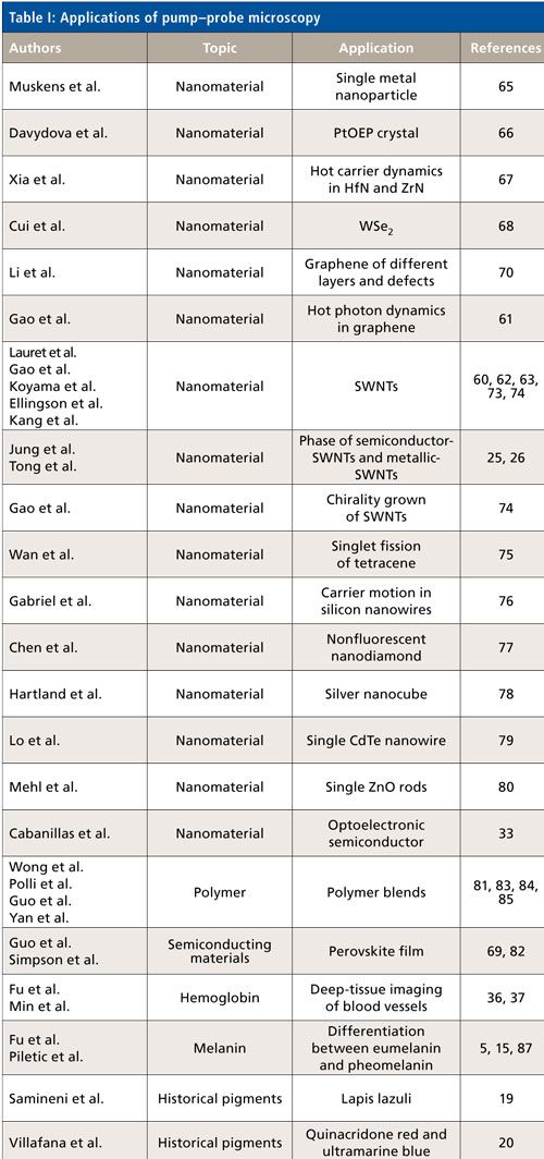
With its superior detection sensitivity, chemical specificity and spatial-temporal resolution, pump–probe microscopy has been used to study pigmentation (14), microvasculature (14), ultrafast relaxation in SWNTs (23–26,60–63), single semiconductor and metal nanostructures (64,65), and other nanomaterials (66–69). Table I summarizes representative applications in various areas. These applications are reviewed in more detail in the following sections.
Semiconducting Nanomaterials and Graphene
Pump–probe microscopy provides a vivid image of graphene with high sensitivity. Muskens and colleagues have demonstrated the study of a single metal nanoparticle by combining a high-sensitivity femtosecond pump–probe setup with a spatial modulation microscope (65). Besides metal nanoparticles, Zhang and colleagues also imaged graphene with single-layer sensitivity through transient absorption, whereas other techniques such as high-resolution transmission electron microscopy, scanning electron microscopy, and scanning tunneling microscopy proved to be cumbersome in sample preparation (70). In their work, they achieved high speed (2 μs/pixel) imaging of graphene on various substrates under ambient condition and even in living cells and animals. Interestingly, the intensity of the transient absorption images is found to linearly increase with the number of layers of graphene. In Figure 5a, in the TA image of graphene, we can clearly observe the location of graphene defects and that of different layers. It only takes a few seconds to acquire a TA image of graphene. In addition, with polyethylene glycol used to functionalize graphene oxide, these well-dispersed particles have shown the capability for in vitro and ex vivo imaging in Chinese hamster ovary (CHO) cells (70).
Pump–probe microscopy is also exploited to study SWNTs. Carbon nanotubes, especially single-wall carbon nanotubes, have attracted much attention in the last two decades (71,72). The excellent properties of SWNTs in thermal conductivity, electronics, optics, and mechanics make them appealing. Pump–probe microscopy has proved to be a powerful tool to explore the intrinsic photochemical properties of single-wall carbon nanotubes. Accurate detection of carrier dynamics in these nanostructures is essential for understanding and developing their optoelectronic properties. Lauret and colleagues reported for the first time the time-resolved study of carrier dynamics in single-wall carbon nanotubes by means of two-color pump–probe experiments under resonant excitation with a selective injection of energy in the semiconducting nanotubes (73). Jung and colleagues for the first time exploited the phase of the pump–probe signal as a contrast to study SWNTs (25). Later Tong and coworkers showed that transient absorption microscopy offers a label-free approach to image both semiconducting and metallic SWNTs in vitro and in vivo in real time with submicrometer resolution, by choosing appropriate near-infrared wavelengths (26). Semiconducting and metallic SWNTs exhibit transient absorption signals with opposite phases. Figure 5b shows the transient absorption image of DNA-SWNTs internalized by CHO cells, where gray represents the transmission image. The different colors in the image result from different phases representing two different kinds of SWNTs: green represents semiconducting SWNTs and red represents metallic SWNTs. Gao and colleagues reported transient absorption microscopy experiments on individual semiconducting SWNTs with known chirality grown by chemical vapor deposition (CVD) with diffraction-limited spatial resolution and subpicosecond temporal resolution (74)].
Pump–probe microscopy has also been extensively applied to study nanoparticles and nanowires. Figure 5c presents visualization of singlet fission by observing the decay-associated spectra of the triplet (red) and singlet (green) excitons of tetracene. The curves in Figure 5c were obtained by global analysis of the ensemble transient absorption spectra (75). As shown in Figure 5d, pump–probe microscopy has been used to demonstrate the spatial kinetics of silicon nanowires (76). In addition, nanodiamonds and nanocubes are of great interest to researchers. Figure 5e demonstrates 3D transient absorption microscopic images of gold nanodimonds in living cells (77). Figure 5f shows a fast decay of silver nanocubes resulting from electron-phonon coupling and subsequent modulations from the coherently excited breathing mode (78).
Pump–probe microscopy examines intrinsic excited state dynamics of semiconductors. Lo and colleagues demonstrated transient absorption measurements on single CdTe nanowires, and they showed for the first time that acoustic phonon modes were fast because of the efficient charge carrier trapping at a lower excitation intensity (79). Mehl and coworkers (80) reported pump–probe microscopy of the individual behaviors of single ZnO rods at different spatial locations. Dramatically different recombination dynamics were observed in the narrow tips compared with dynamics in the interior. Cabanillas-Gonzalez and colleagues (33) highlighted the contribution of pump–probe spectroscopy to the understanding of the elementary processes taking place in organic based optoelectronic devices. They further illustrated three fundamental processes (optical gain, charge photo-generation and charge transport). This work opens new perspectives for assessing the role of short-lived excited states on organic device operation. Polli and coworkers developed a new instrument approach by combining broadband femtosecond pump–probe spectroscopy and confocal microscopy, enabling simultaneously high temporal and spatial resolution (81). Guo and colleagues (82) reported spatially and temporally resolved measurements of perovskite by ultrafast microscopy. This work underscores the importance of the local morphology and establishes an important first step toward discerning the underlying transport properties of perovskite materials.
Pump–probe microscopy also provides new insight into the properties of polymer blends by directly accessing the dynamics at the interfacing between different materials (83).Guo and colleagues (84) elucidated the exciton structure, the dynamics, and the charge generation in the solution phase aggregate of a low-bandgap donor-acceptor polymer by transient absorption. The technique enables important applications in controlling morphology. Using ultrafast microscopy, Yan and colleagues proved that adding an amorphous content to highly crystalline polymer nanowire solar cells could increase the performance (85).
Heme-Containing Proteins and Melanins
Responsible for transporting oxygen, hemoglobin is a metalloprotein in the red blood cells of vertebrates. It is an assembly of four globular protein subunits. Each subunit is composed of a protein tightly associated with a heme group. A heme group consists of an iron ion in a porphyrin. It is well known that the heme group portrays strong absorption yet weak fluorescence. These properties make label-free pump–probe microscopy imaging of hemoglobin an ideal approach. Fu and colleagues (36) demonstrated label-free deep tissue imaging of microvessels in nude mouse ear. They chose a pump beam of 775 nm and a probe beam of 650 nm, and successfully harvested two-color TPA images of microvasculature at different depths with a penetration depth of ~70 µm. In their following-up study, they chose a longer probe beam of 810 nm to differentiate oxyhemoglobin and deoxyhemoglobin as shown in Figure 6a. Beyond two-photon absorption, other procedures can also be applied to observe microvessels. Min and colleagues conducted stimulated emission imaging of microvasculature network in a mouse ear based on the endogenous hemoglobin contrast by choosing the pump beam as 830 nm (two-photon excitation of Soret band) and probe beam as 600 nm (one-photon stimulated emission of Q-band) (see Figure 6b) (37).
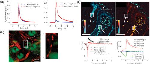
Figure 6: Imaging microvascular and melanomas by pump–probe microscopy: (a) Pump–probe microscopy is applied to differentiate oxyhemoglobin and deoxyhemoglobin. ESA signal from oxyhemoglobin and deoxyhemoglobin with pump = 810 nm (10 mW) and probe = 740 nm (6.4 mW) (left). ESA signal from oxyhemoglobin and deoxyhemoglobin with pump = 740 nm (2.4 mW) and probe = 810 nm (10 mW) (right). Adapted with permission from reference 36 (copyright 2008 Society of Photo-Optical Instruction Engineers). (b) Ex vivo imaging of microvasculature network of a mouse ear based on endogenous hemoglobin contrast. Red, blood vessel network; green, surrounding sebaceous glands. Pump = 830 nm (~20 mW, two-photon excitation of Soret band), probe = 600 nm (~3 mW, one-photon stimulated emission of Q-band of hemoglobin). Adapted with permission from reference 37. (c) Pump–probe image of a compound nevus at 0-fs (left) and 300-fs (right) interpulse delay (top). Regions containing eumelanin have positive signal (red/orange). Pump–probe time delay traces comparing tissue regions of interest 1 and 2 (white boxes in top) with pure solution melanins (bottom). The first three principal components found in tissue pump–probe signals (loadings plot, right). The first two components account for more than 98% of the variance. Pump = 720 nm, probe = 810 nm. Scale bar = 100 μm. Adapted with permission from reference 6.
Pump–probe microscopy could also be used to differentiate different melanins. Melanins generally come in two polymeric forms: eumelanin (black) and pheomelanin (red/brown). Their biosynthetic pathways involve the oxidation of tyrosine leading to the formation of indoles and benzothiazines (87). Pheomelanin is reddish yellow, and it exhibits phototoxic and pro-oxidant behavior (88). Eumelanin is a brown–black pigment that is substantially increased in melanoma. Therefore imaging the microscopic distribution of eumelanin and pheomelanin could be used to separate melanomas from benign nevi in a highly sensitive manner (16). The differences of the signals of these two different melanins are shown in Figure 6c. Eumelanin has an abrupt positive absorption corresponding to excited-state absorption or two-photon absorption, the same as hemoglobin, whereas pheomelanin gives a negative bleaching signal in Figure 6c. Their difference arises from stimulated emission or ground-state bleaching, respectively (6).
Historical Pigments
Pump–probe microscopy could be further exploited to identify pigments in historic artworks. The approach could extract molecular information with high resolution in 3D making it attractive in this application, since accurate identification is of great value for authentication and restoration (19–21). Villafana and colleagues studied the layer structure of a painting by femtosecond pump–probe microscopy, since the variety of pigments in the artist’s palate is enormous compared with the biological pigments present in skin (20). This is a great approach to extract microscopic information for a broad range of cultural heritage applications. Samineni and colleagues (19) were the first to conduct a pump–probe study of lapis lazuli, a semi-precious rock, by analyzing the multiexponential decay behavior as shown in Figures 7a and 7b. The ratio of amplitude for short decay constant to that of long decay constant for the synthetic ultramarine pigment is 6.6 ± 0.35, while that for natural lapis lazuli is 2.5 ± 0.05. Thus, they readily could be distinguished.
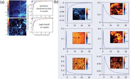
Figure 7: Imaging artistic pigments by pump probe microscopy: (a) Transient absorption images of synthetic ultramarine in acrylic (golden artist colors GMSA 400, top) and lapis lazuli in casein (Kremer pigments 10530, bottom) and the corresponding pump–probe delay traces in the indicated region of interest (white rectangle) where the line indicates double-exponential fits. Scalar bar = 100 µm. S/N = 100. Adapted with permission from reference 19 (copyright 2012 Optical Society of America). (b) Graphs showing pump probe dynamics in test samples with the pigments lapis lazuli, vermilion, caput mortuum, quinacridone, phthaloblue, and indigo. Adapted with permission from reference 21.
Outlook
Looking into the future, we predict the following advancements of this emerging technology. First, compact and low-cost pump–probe microscopy will be developed and made commercially available for broad use of this technique by nonexperts. Second, handheld pump–probe imaging system will be developed to assist precision surgery in the clinic. Third, important applications of pump–probe microscopy will be identified, in which the decay kinetics are used to study cellular development and disease stage. These advances will make pump–probe microscopy an important member of the nonlinear optical microscopy family with broad use in biology, medicine, and materials science.
References
- A.H. Zewail, Science 242(4886), 1645–1653 (1988).
- D. Zhong et al., Proc. Natl. Acad. Sci. U.S.A.98(21), 11873–11878 (2001).
- S.K. Pal et al., J. Phys. Chem. B106(48), 12376–12395 (2002).
- T. Ye, D. Fu, and W.S. Warren, Photochem. Photobiol. 85(3), 631–645 (2009).
- W. Min et al., Ann. Rev. Phys. Chem.62, 507 (2011).
- T.E. Matthews et al., Science Translational Medicine3(71), 71ra15-71ra15 (2011).
- P.A. Elzinga et al., Appl. Spectrosc.41(1), 2–4 (1987).
- T. Katayama et al., Langmuir 30(31), 9504–9513 (2014).
- M. Hu and G.V. Hartland, J. Phys. Chem. B106(28), 7029–7033 (2002).
- G. Seifert et al., Applied Physics B71(6), 795–800 (2000).
- G.V. Hartland, Chemical Reviews111(6), 3858–3887 (2011).
- M.J. Simpson et al., J. Invest. Derm. 133(7), 1822–1826 (2013).
- C. Dong et al., Biophys. J.69(6), 2234 (1995).
- D. Fu et al., J. Biomed. Optics12(5), 054004 (2007).
- L. Wei and W. Min, Anal. Bioanal. Chem.403(8), 2197–2202 (2012).
- T.E. Matthews et al., Biomed. Optics Express2(6), 1576–1583 (2011).
- F.E. Robles et al., Biomed Optics Express6(9), 3631–3645 (2015).
- M.J. Simpson et al., J. Phys. Chem. Letters 4(11), 1924–1927 (2013).
- P. Samineni et al., Optics Letters37(8), 1310–1312 (2012).
- T.E. Villafana et al., Proc. Natl. Acad. Sci.111(5), 1708–1713 (2014).
- F. Martin, Physics World26(12), 19 (2013).
- S. Link et al., Phys. Rev. B61(9), 6086 (2000).
- L. Huang, H.N. Pedrosa, and T.D. Krauss, Phys. Rev. Letters93(1), 017403 (2004).
- I. Robel, B.A. Bunker, and P.V. Kamat, Adv. Mater.17(20), 2458–2463 (2005).
- Y. Jung et al., Phys. Rev. Letters105(21), 217401 (2010).
- L. Tong et al., Nat. Nanotech.7(1), 56–61 (2012).
- R. Berera, R. van Grondelle, and J.T. Kennis, Photosynth. Res.101(2-3), 105–118 (2009).
- D.Y. Davydova et al., Laser & Photonics Reviews10(1), 62–81 (2016).
- B. Nechay et al., Rev. Scient. Inst.70(6): p. 2758–2764 (1999).
- J. Jahng et al., Appl. Phys. Lett.106(8), 083113 (2015).
- L. Huang and J.-X. Cheng, Ann. Rev. Mat. Res. 43(1), 213–236 (2013).
- L. Tong and J.-X. Cheng, Materials Today14(6), 264–273 (2011).
- J. Cabanillas-Gonzalez, G. Grancini, and G. Lanzani, Adv. Mater.23(46), 5468–5485 (2011).
- H.E. Lessing and A. Von Jena, Chem. Phys. Lett.42(2), 213–217 (1976).
- A. Von Jena and H.E. Lessing, Chem. Phys. Lett.78(1), 187–193 (1981).
- D. Fu et al., J. Biomed. Opt.13(4), 040503 (2008).
- W. Min et al., Nature461(7267), 1105–1109 (2009).
- S.W. Hell and M. Kroug, Appl. Phys. B60(5), 495–497 (1995).
- S. Bretschneider, C. Eggeling, and S.W. Hell, Phys. Rev. Lett. 98(21), 218103 (2007).
- S. Chong, W. Min, and X.S. Xie, J. Phys. Chem. Lett.1(23), 3316–3322 (2010).
- K.L. Blythe et al., Phys. Chem. Chem. Phys.15(12), 4136–4145 (2013).
- S. Zink et al., Microscopy Today21(04), 14–18 (2013).
- R. van Grondelle, Biochim. Biophys. Acta. 811(2), 147–195 (1985).
- B. Gao, G.V. Hartland, and L. Huang, J. Phys. Chem. Lett.4(18), 3050–3055 (2013).
- M.N. Slipchenko et al., J. Biophoton.5(10), 801–807 (2012).
- D.B. Murphy and M.W. Davidson, in fundamentals of Light Microscopy and Electronic Imaging (John Wiley & Sons, Inc., 2012), pp. 1–19.
- P. Wang et al., Nature Photonics7, 449–453 (2013).
- J. Miyazaki, K. Kawasumi, and T. Kobayashi, Optics Lett. 39(14), 4219–4222 (2014).
- E.M. Grumstrup et al., Chem. Phys.458, 30–40 (2015).
- E.S. Massaro, A.H. Hill, and E.M. Grumstrup, ACS Photonics3(4), pp 501–506 (2016).
- G.I. Redford and R.M. Clegg, J. Fluoresc. 15(5), 805–815 (2005).
- M.A. Digman et al., Biophys. J.94(2), L14–L16 (2008).
- C. Stringari et al., Proc. Natl. Acad. Sci.108(33), 13582–13587 (2011).
- F.E. Robles et al., Optics Express20(15), 17082–17092 (2012).
- F. Fereidouni et al., J. Biophoton.7(8), 589–596 (2014).
- F. Fereidouni, A.N. Bader, and H.C. Gerritsen, Optics Express20(12), 12729-12741 (2012).
- D. Fu and X.S. Xie, Anal. Chem.86(9), 4115–4119 (2014).
- J. Miyazaki, K. Kawasumi, and T. Kobayashi, Rev. Scientif. Inst.85(9), 093703 (2014).
- D. Fu et al., J. Biomed. Optics13(5), 054036–054036-7 (2008).
- T. Koyama et al., J. Luminesc.169 Part B, 645–648 (2016).
- B. Gao et al., Nano Lett.11(8), 3184–3189 (2011).
- R.J. Ellingson et al., Phys. Rev. B71(11), 115444 (2005).
- S.J. Kang et al., Nature Nanotechnol.2(4), 230–236 (2007).
- M.A. van Dijk, M. Lippitz, and M. Orrit, Phys. Rev. Lett.95(26), 267406 (2005).
- O.L. Muskens, N. Del Fatti, and F. Vallée, Nano Lett.6(3), 552–556 (2006).
- D.Y. Davydova et al., Chem. Phys.464, 69–77 (2016).
- H. Xia et al., Solar Energy Materials and Solar Cells150, 51–56 (2016).
- Q. Cui et al., ACS Nano8(3), 2970–2976 (2014).
- M.J. Simpson et al., J. Phys. Chem. Lett. 7(9), 1725–1731 (2016).
- J. Li et al., Scientific Reports5, 12394 (2015).
- M. Terrones et al., Nature 388(6637), 52–55 (1997).
- A. Bachtold et al., Science 294(5545), 1317–1320 (2001).
- J.S. Lauret et al., Phys. Rev. Lett.90(5), 057404 (2003).
- B. Gao, G.V. Hartland, and L. Huang, ACS Nano6(6), 5083–5090 (2012).
- Y. Wan et al., Nature Chem.7(10), 785–792 (2015).
- M.M. Gabriel et al., Nano Lett.13(3), 1336–1340 (2013).
- T. Chen et al., Nanoscale5(11), 4701–4705 (2013).
- G.V. Hartland, Chem. Sci.1(3), 303–309 (2010).
- S.S. Lo et al., ACS Nano6(6), 5274–5282 (2012).
- B.P. Mehl et al., J. Phys. Chem. Lett.2(14), 1777–1781 (2011).
- D. Polli et al., Advanced Materials22(28), 3048–3051 (2010).
- Z. Guo, et al., Nature Commun.6, 7471(2015).
- C.Y. Wong et al., J. Phys. Chem. C117(42), 22111–22122 (2013).
- Z. Guo et al., J. Phys. Chem. B119(24), 7666–7672 (2015).
- H. Yan et al., Advanced Materials27(23), 3484–3491 (2015).
- D. Fu et al., Optics Lett.32(18), 2641–2643 (2007).
- I.R. Piletic, T.E. Matthews, and W.S. Warren, J. Chem. Phys.131(18), 181106 (2009).
- J.D. Simon et al., Pigment Cell & Melanoma Research22(5), 563–579 (2009)
Pu-Ting Dong and Ji-Xin Cheng are with Purdue University in Indiana. Please direct correspondence to: jcheng@purdue.edu

New Raman Spectroscopy Method Enhances Real-Time Monitoring Across Fermentation Processes
April 15th 2025Researchers at Delft University of Technology have developed a novel method using single compound spectra to enhance the transferability and accuracy of Raman spectroscopy models for real-time fermentation monitoring.
New Multi-Spectroscopic System Enhances Cultural Heritage Analysis
April 2nd 2025A new study published in Talanta introduces SYSPECTRAL, a portable multi-spectroscopic system that can conduct non-invasive, in situ chemical analysis of cultural heritage materials by integrating LIBS, LIF, Raman, and reflectance spectroscopy into a single compact device.