The Role of Naturally Occurring Stable Isotopes in Mass Spectrometry, Part II: The Instrumentation
In the second installment of this tutorial, the authors explain the instrumentation for measuring naturally occurring stable isotopes, specifically the magnetic sector mass spectrometer.

In the second installment of this tutorial, the authors explain the instrumentation for measuring naturally occurring stable isotopes, specifically the magnetic sector mass spectrometer. This type of instrument remains unrivaled in its performance for isotope ratio mass spectrometry (IRMS), and the reader is reminded of its operation and its technical advantages for isotope measurements.
The first installment of this series focused on the theoretical aspects of stable isotopes and the calculation of their distribution patterns. In this second chapter, we will look at the technical measurement of stable isotopes using low-resolution magnetic sector mass spectrometers. We focus on magnetic sector instruments primarily because this mass spectrometer remains unrivaled in its performance for isotope ratio mass spectrometry (IRMS). Gas isotope ratio measurements require a much greater precision than that obtainable from other low-resolution instruments such as quadrupoles. The sector mass spectrometer also still prevails in other areas such as process control gas analysis (that is, blast furnace top gas monitoring or coke oven gas analysis), which demand exceptional long-term stability and a high tolerance of changes in the nature of the sample gas from oxidizing to reducing behavior (1).
Furthermore, in their most sophisticated form, magnetic sector instruments remain the gold standard for petroleum analysis, ultratrace level determination of organic pollutants such as polychlorinated dibenzo-para-dioxins (PCDD) and polychlorinated dibenzofurans (PCDF) by gas chromatography (GC)–MS. The second reason for concentrating on magnetic instruments in this tutorial series is the increasing difficulty of finding detailed descriptions of the sector instrument's theory and construction, particularly because the manufacturers' manuals devote less and less space to these topics. Furthermore, different classes of mass analyzers, such as quadrupoles and their derivatives, have increased in popularity to the extent that now there is a whole generation of MS practitioners, many of whom have never considered the sector instruments. Therefore, the present authors found it worthwhile to remind mass spectrometrists of the technical principles of an MS technique that still dominates particular areas of science. Readers interested in the technical descriptions of the other mass analyzers (for example, quadrupoles, ion traps, time-of-flight instruments, ion cyclotron resonance, and orbitraps) are referred to references 2 and 3.
With this in mind, this short tutorial seeks to collate details of the low-resolution magnetic sector instrument with the view of offering current and potential users of these instruments a description of their components in greater depth than is offered by elementary resources. For these, the components of the mass spectrometer will be taken as the gas inlet system, the ion source, the magnetic sector, and the detector. The construction of the vacuum chamber and its associated components, such as pumps and vacuum gauges, will not be discussed, nor will any detailed description of the electronics be given.
Gas Inlet Systems
Before we delve into the inner workings of the magnetic sector instrument, it is useful to spend a few moments on the design of the interface between the gaseous sample and the vacuum of the mass spectrometer. To understand the transport and pressure reduction elements involved requires familiarity with vacuum techniques, and in particular the characteristics of gas flow over a wide range of working pressures. A full discussion of the vacuum science and technology required is outside the scope of this tutorial; however, the salient points for our purposes are that the rate of material flow through a vacuum pump (throughput) is given by

where S is the pump speed (usually quoted in liters per second) and P the working pressure of the pump (usually quoted in millibar). Similarly, the rate of material flow though a tube or other element of the vacuum system is given by

where C is the conductance of the element, which is determined by both its physical dimensions and the operating pressure, and ΔP is the pressure drop across the element. For a more comprehensive discussion, the reader is referred to www.vacuumlab.com, and the references that are cited there.
Although more details on the ionization source will be explained in the following section, it is important, at this point, to estimate the gas flow requirements of the mass spectrometer, to discuss sample introduction systems compatible with these flow rates. The pressure in the main part of the vacuum chamber of the mass spectrometer is typically ~10–6 mbar. With a diffusion or turbomolecular pump, a pumping speed of 100 L/s is readily available, and for a total conductance of the three apertures in the ionization chamber of about 0.7 L/s, the pressure in the ionizing region is expected to be about 1.4 x 10⁻⁴ mbar, or approximately two orders of magnitude higher than that in the vacuum system proper. In passing, it is noted that from this calculation the throughput of sample gas is estimated to be 10–4 mbarL/s, or about 5 nmol/s. Because sampling is usually performed from approximately atmospheric pressure, the required gas throughput necessitates a leak element with a conductance of 10–7 L/s for direct sampling. The obvious choice for this is a capillary. Representative dimensions are given in Table I.
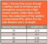
Table I
Capillaries of the smaller diameters are prone to blockage, and those with larger diameters have relatively slow transit times and are therefore not sufficiently responsive if sample switching is required. To overcome this, a two-part inlet system can be used with a bypass line fitted at the junction of the leak elements, which is taken to a vacuum pump (Figure 1). This system has fast response time, but care must be taken in its design if gas samples of widely differing viscosities are to be analyzed. Optimal conditions are obtained if the flow from the sampling point to the tee-piece is viscous, and the flow from the tee-piece to the pump is molecular; however, some mixed flow conditions almost always exist. The pressure at the junction should be in the range 5–10 mbar; hence, a leak element with conductance of about 10–5 mbarL/s is required. A glass sinter is commonly used to provide a compact leak with a conductance in this range.
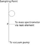
Figure 1: The capillary inlet with a bypass. The performance is set by the dimensions of the elements. Between the sampling point and point P, viscous flow through the capillary dictates the sampling rate. For example, for a tube of 0.25 mm i.d. and 1.5-m long, the sampling rate from atmosphere will be fixed at about 10 mL/min. The element between point P and the vacuum pump, through which flow is molecular, sets the pressure at point P. For the same capillary above, a tube from P to the vacuum pump of internal diameter 6 mm and 1 m long will give a pressure of about 7 mbar at the tee-piece.
A somewhat specialized system that allows for rapid switching between two gas samples is often used in gas IRMS. The samples are held in reservoirs that are each connected to the ion source by a stainless steel capillary, which can be crimped to match the gas throughputs. Interposed between the capillaries and the source is a microvalve arranged such that when one gas line is connected to the source the other is connected to a pump. In this way, gas is continuously bled from both reservoirs, and when stream switching is desired it is only a very small volume, which must be flushed before stable measurements can be made.
In recent years the continuous flow inlet has become fashionable, particularly for the analysis of 13CO2 in breath, but the principle is applicable much more broadly. A typical system incorporates a multiport sampling valve configured with a sampling loop, although a considerable degree of complexity can arise (see for example reference 4). However, all the sampling systems are designed to achieve the same purpose — to introduce a slug of sample gas into a stream of carrier gas. The mass spectrometer samples the carrier gas via an open split.
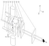
Figure 2: Schematic of a typical ion source showing (A) filament assembly, (B) electron trap, (C) ionization chamber, (D) ion repeller, (E) source magnet, (F) half plates, (G) source slit, and (H) alpha slit. Also shown are the filament and trap currents (If and It), the ion beam leaving the source (Ib), and the potentials defining the electron energy (Vee), The ion energy (Vs), the focus (Vf) and the half-plate differential (Vd).
The Ion Source
A comprehensive discussion of the various types of ion sources used with magnetic sector (and other) instruments has been given by Elliott (5). For isotope ratio work, the type of ion source usually employed is based upon the design of Nier (6,7), which has been used successfully in these applications for many years (Figure 2). The sample gas is introduced into an ionization chamber, which is essentially a closed box, with small holes for the entry and exit of the ionizing electron beam, and also for the ions to exit. The purpose of keeping the ionization chamber as gas-tight as possible is to create a region of relatively high pressure, so that the molecular density is sufficiently high for adequate ionization to occur. The ions exit into the general vacuum chamber, which operates at a lower pressure where the mean free path of the residual gas molecules is sufficiently low that ion scattering is negligible.
An electron beam is generated outside the ionization chamber by thermionic emission from a heated filament. Various filament materials have been used over the years. Tungsten has been popular, but it is not ideal because it has a relatively high work function, and therefore needs a high temperature (approximately 2300 °C) for photoemission to occur. As well, the performance requires a degree of carbonization of the filament, giving high levels of background CO and CO2. Rhenium has been proposed as an alternative, as have refractory oxides mounted on a conducting wire. ThO2-coated iridium was used for many years, but recently has fallen out of favor because thorium emits alpha radiation, and therefore it has been replaced by Y2O3.
The filament is held at a slightly negative potential with respect to the ionization chamber. This potential sets the electron energy, and therefore the ionizing power of the electron beam. Under the influence of this potential, the electrons are accelerated toward the ionization chamber and pass through a narrow slit in one of its walls. The majority of them traverse the ionization chamber and exit through a second aperture in the wall directly opposite. Having passed through this exit hole, they strike the electron trap, which is another electrode set at a positive potential of ~50 V with respect to the ionization chamber, to reduce the likelihood of secondary emission.
The electron beam is collimated by a coaxial magnetic field provided by a pair of magnets. The combination of this field and the electron energy results in the electrons adopting a spiral path through the ionization chamber, and the ionizing region is therefore a cylinder of relatively narrow radius. Besides keeping the ion beam well-defined, the spiral nature of the ionizing electron trajectory has the secondary advantage of increasing the pathlength of the electrons as they traverse the sample gas, with a corresponding increase in the ionization efficiency (although it still remains poor at 10–100 ppm). The ions are extracted through a narrow slit with its major axis parallel to that of the electron beam, and hence a ribbon-like beam of ions, with its long axis aligned with the electron path between filament and trap, is ejected from the ionization region toward the magnet.
The ions formed leave the chamber, which is maintained at a high positive potential (>2000 V) with respect to the rest of the vacuum system. In fact, extraction is achieved by a weak field due to a combination of field interpenetration from the half-plates, which lie just outside the ionizing chamber, and a small electrode sited within it known as the ion repeller. The ion repeller is usually set in the range –20 to +20 V with respect to the ionization chamber; the precise setting usually is determined by empirical optimization of the source behavior.
Having left the ionization chamber, the ion beam is accelerated toward the source slit, which is at ground potential (Figure 1). The half-plates between the ionization chamber and source slit are maintained at an intermediate potential to achieve focusing of the beam at the source slit itself. Additionally, a differential voltage of up to about ±200 V can be applied to the half-plate for beam steering purposes. Finally, the beam passes through an alpha slit, again at ground potential, which limits the angular dispersion in the plane perpendicular to the magnetic field. Further refinements to the ion optic system are sometimes used, including extra beam steering plates, and plates designed to steer and focus the beam in the z-direction.
The operation and maintenance of the ion source requires the user to set and monitor a number of electronic parameters. These are described in more detail later.
Filament Current
As its name suggests, this is the current passing through the filament, causing it to heat to the point where thermionic emission occurs. The filament current depends on the nature of the filament material (its composition and dimensions), but is typically of the order of a few amperes. The amount of emission, and hence the number of electrons available for creating ions, is governed by the magnitude of this current. Therefore, it is regulated by means of a feedback system to stabilize the number of electrons passing through the ionization chamber (see trap current discussion). As the filament ages it often thins, and its resistance rises, causing the filament current to drop. This is sometimes an early indication of a filament that is near the end of its life and about to break.
Source Current
This is due to electrons leaving the filament and colliding with the walls of the ionization chamber, rather than traversing it and reaching the electron trap. In general, for an efficient source the source current should be approximately equal to the trap current. Exceptionally high source currents can indicate a filament that is poorly aligned. However, the practitioner should be aware that a second source of electron flow to the ionization chamber is by "leakage" from the body of the vacuum chamber through the ceramic spacers, which isolate it from the source. Therefore, an abnormally high source current can sometimes indicate contamination or dirt deposited on the source ceramics.
Trap Current
The trap current is due to electrons, which leave the filament and successfully traverse the ionization region and arrive on the electron trap. Generally in the range of 50–500 µA, the trap current is maintained at a steady value using a feedback arrangement to control the voltage applied to the filament, and consequently the filament current and amount of emission. By these means it is possible to obtain trap current stability to better than 0.01%, which is necessary for the measurement of ion currents and ratios to the degree of precision required for isotope ratio work. To protect the filament from burning out due to an excessive demand for trap current, an upper limit on available filament current is usually imposed. If this limit is achieved, the trap regulation fails, and the ion beam exiting the source usually becomes unstable.
Electron Energy
A potential difference is applied between the filament and the ionizing chamber to attract the electrons leaving the filament so that they pass through the ionizing region. This is the so-called electron energy, since it is responsible for imparting sufficient energy to the electrons for them to be able to promote ionization. The magnitude of the electron energy dictates the number and types of positive ions formed. A typical chemical bond has an energy of 450 kJ/mol, corresponding to about 5 eV, and this corresponds to the ionization potential. At electron energies slightly above the ionization potential of the target molecule (soft ionization), little molecular fragmentation occurs, but at higher electron energies (hard ionization), all of the possible molecular fragments are produced. Inspection of the ionization efficiency curves for a number of gases indicate that the maximal positive ion currents for the molecular ion and its fragments occur at very much the same electron energy, which is in the range 50–100 V.
If it is decided to reduce the electron energy to create 'softer' ionization conditions, then the draw of the electrons from the filament through the ionization chamber will be reduced, and the filament current needed to support a given trap current will increase, as will the source current–to–trap current ratio.
Repeller Voltage
This is the potential difference between the repeller plate and the ionization chamber. As noted previously, the voltage applied is usually in the range –20 to +20 V, and is set to optimize performance. The term ion repeller is therefore a misnomer, because when it is operated at a negative potential with respect to the ionization chamber it clearly acts in the opposite manner. As previously mentioned, ions are extracted from the ionization chamber by a weak field due to a combination of field interpenetration from the half-plates, which lie just outside of it and the repeller plate. Somewhat counterintuitively, it is often found that a negative potential applied to the repeller plate optimizes the ion yield. However, the term ion repeller is still in current usage.
When measuring isotope ratios of hydrogen, a relatively large positive voltage is usually chosen to minimize the residence time of the ionized hydrogen molecules in the source chamber, to lessen the formation of H3+ by molecular collisions.
Ion Energy
This is the potential of the ionization chamber with respect to ground (the vacuum system). This voltage (in combination with the magnetic field) determines the radius of flight of the ions through the magnetic sector. The voltage can be scanned to detect ions of different m/z, with higher m/z being selected by lower ion energy. Many of the other ion source parameters must be optimized for specific ion energies, and this somewhat limits the mass range, which can be covered. To achieve the best possible quantitative analysis with a low-resolution sector instrument, the ion energy should be stable to about 10 ppm.

Figure 3: An ion beam in a magnetic field: (a) the mass separation increases with increasing mass; that is, the radius of flight increases with increasing mass; (b) a divergent ion beam is refocused in a magnetic sector.
Half Plate Potentials
The potentials applied to the half plates have two components, a common and a differential mode. The common mode voltage can be varied anywhere between the ion energy and ground. Frequently this voltage is expressed relative to the ion energy rather than ground, and often as a fraction of it. Therefore, if the ion energy is set to +3 kV with respect to ground, a common half plate potential (sometimes called focus potential) of 10% means that +2.7 kV with respect to ground is supplied to the plates. It is best, however, to consult the manufacturer's literature for a definitive description of how it is defined. The differential voltage is used for beam steering, is bipolar, and usually is restricted to a small fraction of the common mode voltage.

Figure 4
Mass Separation by Magnetic Deflection
When particles of mass m (kilograms) and charge q (coulombs) are accelerated from rest through a potential difference V, the loss in potential energy (qV) results in a corresponding gain of velocity v and thus of translational energy (mv2 /2), so that


Figure 5: (a) Scanning the ion beam across the resolving slits by varying the ion source accelerating potential leads to a flat-topped peak if the resolving slit is wider than the focused beam. Calculation of the resolving power is shown in equation 5. (b) Alternatively, the resolution can be calculated directly from the spectrum (see equation 6).
If such a beam of ions is introduced into a magnetic field produced by a sector magnet (basically the shape of a piece of cake sliced into two horizontally like a cream sponge, so that the ion beam can travel between the two halves), each ion experiences a force perpendicular to the (vertical) magnetic field direction and also perpendicular to the ion beam direction. (This is the same force that operates a DC electric motor since a beam of ions can be regarded as an electric current.) The simplest case is when the (horizontal) beam enters the sector field at right angles to the (vertical) sector boundary, when the magnitude of the magnetic force on an ion is given by Lorentz's law as (Bqv), where B is the magnetic field strength. This causes the ion to travel in a circular trajectory in which this magnetic force is just balanced by the centripetal force (mv2 /r) associated with the circular motion where r is the radius of the orbit. Then:
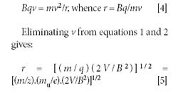
where mu/e is a constant = 1.0364 x 10⁻⁸ kg/C. If V is in volts and B is in tesla (T), r is in meters (an example of the coherence property of SI units). For a singly charged nitrogen molecule (m/z = 28) that has been accelerated through 2200 V and traversing a magnetic field of 0.4 T, the radius is found to be 0.09 m (9 cm).
Clearly, as seen from equation 5, the radius of flight increases with increasing mass (for a given charge), and on this basis the mass separation by a magnetic sector is often depicted as shown in Figure 3a. A magnetic sector, however, does more than simply separating ions in physical space, and it has properties beyond those of a mass filter such as a quadrupole. To illustrate this, we modified the diagram to show the incident ions not as a single ray, but as a divergent beam (Figure 3b). The figure illustrates that the magnetic sector also has the property of refocusing the ion beams. With the simple pole pieces shown, the focusing is not perfect, and is not as effective for the low masses as for the high ones. The ion beam divergence, however, is greatly exaggerated in the diagram (in a real instrument, the divergence angle is less than 1°). The position of the image point depends not only on the distance between the object (in this case the source slit) and the incident pole face of the magnet, and the radius of flight in the magnetic field, but also on the angle of the incident and exit pole faces. The condition for a focused image to be obtained is (8)

where a and b are the object and image distances, and α and β are the angles between the "central" ray of the ion beam and the normals to the incident and exit pole faces, respectively, and θ the angle through which the ion beam is deflected.
Furthermore, the angle of the pole faces has consequences for the trajectories of the ions in a direction parallel to the magnetic field (conventionally, the magnetic field is said to define the z-axis of the system, with the ions being separated in the x-y plane). If the normal is on the outside of the beam with respect to the center of curvature in the magnetic field the angle is taken to be positive, and the effect is to focus the beam in the z-direction. Conversely, if the normal is on the same side of the center of curvature the angle is said to be negative, and the beam is defocused. From the diagram in Figure 4, it can be seen that for this case the low mass beam is z-focused as it leaves the magnet, while the high mass beam will be caused to diverge slightly in the z-direction.
These properties have been exploited in many analyzer designs. In particular, the geometry where the angle of deflection (θ) is 90° and the entrance and exit angles (αand β) are set to 26.57°, the focal points in the x-y plane and in the z-plane are coincident. This geometry is sometimes known as a double-focusing system (although the same terminology is also used for instruments that focus for angular divergence using a magnet, and also ion velocity using an electric sector).
Flat-Topped Peaks
The resolving (detector) slit is placed at the point where the image of the source slit is located in the x-y plane. The ion beams can be scanned across the resolving slits by varying either the ion source accelerating potential or the magnetic field. If the resolving slit is wider than the focused beam, then the output of the amplifier from such a scan is in the form of a flat-topped peak (Figure 4a).
The advantage of operating in this mode is that unit resolution is achieved (that is, ions of a particular integral value of m/z only are selected), but any small drifts in magnetic field or accelerating potential are insufficient to cause instability in the detected signal.
Because any slight misalignment in the ion optical system can have a profound effect on the precise point where the image is formed, it is typical to make the magnet position adjustable. When the instrument is set up, the optimal magnet position is locating by observing the quality of the flat-topped peaks (that is, by finding the position for which the top is flattest and the sides are steepest). The process of optimization is often more difficult than might be anticipated, especially for operators inexperienced in the task.
Dispersion and Resolution
The dispersion of the ion optical system is defined as the separation between adjacent mass foci. Two masses are said to be resolved by the instrument if their beams are such that only one of them passes through the detector slit. Clearly, the maximum resolution would be achieved if the resolving slit was exactly the same as the beam width. However, as has been stated earlier, this is not the mode of operation with flat-topped peaks (Figure 5a). In these instruments, the resolving power R is the largest m/z ratio at which adjacent peaks of equal height have a 10% valley between them. This is equivalent to saying the m/z ratio at which the width of the peak measured at 5% of its height is equal to the separation between adjacent peaks. Clearly, the width of the resolving slit is a major factor in determining the resolution of such an instrument, as is the quality of the ion-optics alignment.
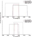
Figure 6: Stylized scan output for a collector designed to monitor isotope ratios of N2 and CO2. In this system, the central resolving slit width is 0.4 mm and that of each of the outer slits is 1.1 mm. Note the effect of the difference in spatial position between the N2 and CO2 mass clusters.
From the peak shape, it is possible to obtain estimates of the beam width, slit width, and working resolution of the instrument. The peak is scanned and the positions of the 5% and 95% peak-heights are noted. As an example, a voltage scan performed across m/z 44 on a 6-cm radius instrument is shown in Figure 5a. The 5% points occur at 2696.7 (V1) and 2723.3 V (V2), and the 95% points at 2703.3 (V3) and 2716.7 V (V4). From these are calculated
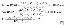
Note the alternative expression for resolution,
R = radius/(slit + beam width)
A different method of measuring the resolution, useful if the absolute scale of the x-axis is unknown, is shown in Figure 5b. Here the width of the peak at 5% height and the separation between adjacent mass numbers are measured directly from the spectrum. In this example, showing peaks at m/z 45 and 44 where s = 99 and d = 43 units, the resolution is calculated as

Abundance Sensitivity
In the preceding discussion, it was assumed that the ion beam distribution is well defined in space, and the overlap between adjacent beams for m/z well below the resolution was assumed to be negligible. This is not the case — there are many reasons why the ions of a particular mass might contribute to the adjacent mass number. The measure of this is termed the abundance sensitivity, and it is quite simply defined as the fractional intensity of a peak appearing at the neighboring position. Typically, the abundance sensitivity of the instrument should be a few parts per million (ppm).
The Collector
The ion collector is generally simple. It comprises a resolving slit (usually placed at the refocusing point as described earlier) and behind it a detector. Although electron multipliers can be used as a detecting element, the requirements of high stability and precision of current applications usually demand that a Faraday bucket (9) (also called a Faraday cup) is used. Electrons ejected from the material of the bucket by the incoming ions are suppressed either by an electric field (a plate with a potential of about –70 V with respect to ground) or by small magnets.
More than one collector can be fitted to the instrument to detect several masses simultaneously. For example, in gas IRMS research, a triple collector set to monitor three adjacent m/z values is often used, and the ion energy changed to select the particular mass group of interest. Substitution of values in the mass spectrometer equation will show, however, that the collector spacing is a function of the masses being measured. This can be partially overcome by making the two outer resolving slits much wider than the central one. Using this approach it is possible to construct a collector that can be used for measuring the stable isotopes of nitrogen (as nitrogen gas at m/z 28, 29, and 30), carbon or oxygen (as CO2 at m/z 44, 45, and 46) and sulfur (as SO2 at m/z 64 and 66). The effect of lowering the resolving power of two of the three detectors is shown in Figure 6. Note the difference in the overlap between the lowest and highest working m/z values for this particular design.
Conclusion
In the preface to the second edition of his book Mass Spectra and Isotopes (10), the pioneering mass spectrometrist F.W. Aston wrote: "Since the publication of the first edition in 1933 ... the subject may be said to have been closed. All the elements have now been analyzed, and my main concern in writing this book is to tell how this has been done." At the time, the explosion in the applications of mass spectroscopy in chemical and biochemical analysis could not have been foreseen. In some ways a similar comment might be applied today to the low resolution magnetic sector instrument, with many MS practitioners dismissing them as old-fashioned and obsolete. However, these instruments are irreplaceable in certain situations where a high degree of precision and long-term stability is required. Magnetic sector instruments are also indispensable for the isotopic analysis of trace metals where an inductively coupled plasma (ICP) source is commonly used because they can be operated in high-resolution mode, which will allow measurements to be made in the presence of interfering species, not possible with mass analyzers of lower resolution, Although dismissed by some as "dinosaurs," these instruments are far from extinct, and for those involved in the business of measuring isotopes, a thorough appreciation of their operation is necessary if an analytical performance of the highest quality is to be achieved.
The next installment of this tutorial will explain in more detail the calculation methods for obtaining an isotopic composition from a sample.
Professor Dietrich Volmer is Head of the Bioanalytical Sciences department at the Medical Research Council's Human Nutrition Research institute in Cambridge, United Kingdom. He is interested in different areas of biological mass spectrometry, including biomarkers, metabolomics, and structural elucidation techniques. Dr. Les Bluck is a senior faculty member in Dr. Volmer's department, with strong interests in stable isotope tracer techniques and physiological modeling.
References
(1) T. Kotiaho, J. Mass Spectrom. 31, 1–15 (1998).
(2) D.A. Volmer and L. Sleno, Spectroscopy 20(11), 20–26 (2005).
(3) D.A. Volmer and L. Sleno, Spectroscopy 20(12), 90–95 (2005).
(4) T. Preston and C. Slater, Proc. Nutrition Soc. 53, 363–372 (1994).
(5) R.M. Elliott, "Ion Sources," in Mass Spectrometry, C.A. McDowell, Ed. (McGraw-Hill, New York, 1963).
(6) A.O. Nier, Rev. Sci. Instrum. 11, 212–216 (1940).
(7) A.O. Nier, Rev. Sci. Instrum. 18, 398–411 (1947).
(8) H.A. Enge, "Deflecting Magnets," in Focusing of Charged Particles, vol. 2, A.L. Septier, Ed. (Academic Press, New York, 1967).
(9) D.W. Koppenaal, C.J. Barinaga, M.B. Denton, R.P. Sperline, G.M. Hieftje, G.D. Schilling, F.J. Andrade, and J.H Barnes IV, Anal. Chem. 418A (2005).
(10) F.W. Aston, Mass Spectrometry and Isotopes, 2nd ed. (Edward Arnold, London, 1942).

New Raman Spectroscopy Method Enhances Real-Time Monitoring Across Fermentation Processes
April 15th 2025Researchers at Delft University of Technology have developed a novel method using single compound spectra to enhance the transferability and accuracy of Raman spectroscopy models for real-time fermentation monitoring.