The Importance of Routine Maintenance in ICP-MS
The following article is adapted from a chapter in the author’s textbook, Practical Guide to ICP-MS and Other AS Techniques: A Tutorial for Beginners, published by CRC Press (ISBN: 9781032035024). More information about the book can be found at the following link: https://www.routledge.com/Practical-Guide-to-ICP- MS-and-Other-Atomic-Spectroscopy-Techniques-A-Tutorial/Thomas/p/ book/9781032035024#
The components of an inductively coupled plasma (ICP) mass spectrometer are generally more complex than other atomic spectroscopic techniques, and as a result, more time is required to carry out routine maintenance to ensure that the instrument is performing to the best of its ability. Some tasks involve a simple visual inspection of a part, whereas others involve cleaning or changing components on a regular basis. However, routine maintenance is such a critical part of owning an ICP-mass spectroscopy (MS) system that it can impact both the performance and the lifetime of the instrument, particularly with complex samples.
The fundamental principle of ICP-MS, which gives the technique its unequalled isotopic selectivity and sensitivity, also unfortunately contributes to some of its weaknesses. The fact that the sample “flows into” the spectrometer and is not “passed by it,” such as flame atomic absorption (AA) and radial inductively coupled plasma optical emission spectroscopy (ICP-OES), means that the potential for thermal problems, corrosion, chemical attack, blockage, matrix deposits, and drift is much higher than with the other atomic spectrometry (AS) techniques. However, being fully aware of this fact and carrying out regular inspection of instrumental components can reduce and sometimes eliminate many of these potential problem areas. There is no question that a laboratory which initiates a routine maintenance schedule stands a much better chance of having an instrument ready and available for analysis whenever it is needed, compared to a laboratory that basically ignores these issues and assumes the instrument will look after itself.
Instrumental Components
Let us now look at the areas of the instrument that a user needs to pay attention to. I will not go into great detail but just give a brief overview of what is important, so you can compare it with maintenance procedures of other trace element techniques you are more familiar with. These areas should be very similar with all commercial ICP-MS systems but depending on the design of the instrument and the types of samples being analyzed, the regularity of changing or cleaning components might be slightly different (particularly if the instrument is being used for solid sampling techniques such as laser ablation work). The main areas that require inspection and maintenance on a routine or semi-routine basis include the following:
- Sample introduction system.
- Plasma torch and radio frequency (RF) generator
- Interface region
- Ion optics
- Mass filter
- Detector
- Roughing pumps
- Turbomolecular pumps
- Air/water filters
Other areas of the instrument require less attention, but nevertheless the user should also be aware of maintenance procedures required to maximize their lifetime. They will be discussed at the end of this section.
Note: It is not the intent to go into the fundamental principles of these instrumental components. However, this article will discuss the factors that impact their routine use. It’s also worth emphasizing that the instrument manufacturer should always be consulted with regard to recommendations for specific tasks related to the design of their technology. You might also consider a preventative maintenance (PM) plan, which is basically an insurance policy in the case of any major or catastrophic failures (more details later in the article).
Sample Introduction System
The sample introduction system, comprising the peristaltic/pneumatic pump, nebulizer, spray chamber, and drain system, takes the initial abuse from the sample matrix, and as a result, is an area of the ICP mass spectrometer that requires a great deal of attention. Brennan and associates published a very informative article on how best to maintain the sample introduction system (1). Let us now examine what kind of routine maintenance it requires.
Peristaltic Pump Tubing
If the instrument uses a peristaltic pump, the sample is pumped at about 1 mL/min into the nebulizer. The constant motion and pressure of the pump rollers on the pump tubing, which is typically made from a polymer-based material, ensures a continuous flow of liquid to the nebulizer. However, over time, this constant pressure of the rollers on the pump tubing has the tendency to stretch it, which changes its internal diameter, and, therefore, the amount of sample being delivered to the nebulizer. The impact could be a change in the analyte intensity, and therefore, a degradation in short-term stability.
Therefore, the condition of the pump tubing should be examined every few days, particularly if your laboratory has a high sample workload or if extremely corrosive solutions are being analyzed. The peristaltic pump tubing is probably one of the most neglected areas, so it is absolutely essential that it be a part of your routine maintenance schedule. Here are some suggested tips to reduce pump tubing–based problems:
- Manually stretch new tubing before use.
- Maintain the proper tension on tubing.
- Ensure tubing is placed correctly in the channel of the peristaltic pump.
- Periodically check the flow of sample delivery and throw away tubing if in doubt.
- Replace tubing if there is any sign of wear; do not wait until it breaks.
- With high sample workload, change tubing every day or every other day.
- Release pressure on pump tubing when instrument is not in use.
- Pump and capillary tubing can be a source of contamination.
- Pump tubing is a consumable item—keep a large supply of it on hand.
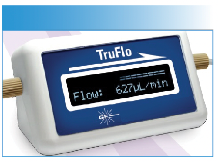
A very useful tool to diagnose any problems associated with the peristaltic pump tubing (or the nebulizer) is a digital thermoelectric flow meter. By inserting this device in the sample line, you always know the actual rate of sample uptake to your nebulizer. This enhances the day-to-day reproducibility of your results and reduces the need to repeat measurements due to a blocked nebulizer, worn pump tubing or incorrect clamping of the pump tube. In addition, the borosilicate glass sample path ensures that there is no memory effect or sample contamination. A commercially-available digital thermoelectric flow meter is shown in Figure 1.
Figure 1: A commercially available digital thermoelectric flow meter to diagnose problems associated with peristaltic pump tubing and nebulizer blockages (courtesy of Glass Expansion).
Nebulizers
The frequency of nebulizer maintenance will primarily depend on the types of samples being analyzed and the design of nebulizer being used. For example, in a cross-flow nebulizer, the argon gas is directed at right angles to the sample capillary tip, in contrast to the concentric or microflow nebulizer, where the gas flow is parallel to the capillary. This can be seen in Figures 2 and 3, which show schematics of a conventional concentric and cross-flow nebulizer, respectively.
FIGURE 2: Schematic of a conventional concentric nebulizer (courtesy of Meinhard Glass Products).
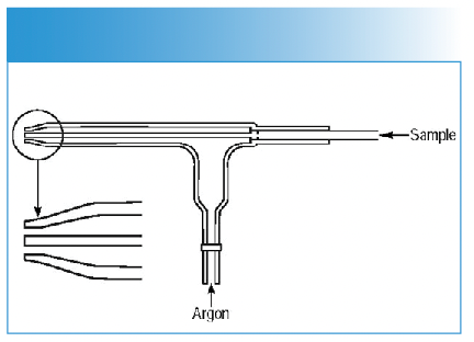
Figure 3: Schematic of a cross-flow nebulizer (courtesy of PerkinElmer Inc.).
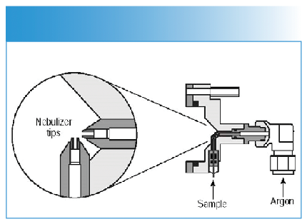
The larger diameter of the liquid capillary and longer distance between the liquid and gas tips of the cross-flow design make it far more tolerant to dissolved solids and suspended particles in the sample than the concentric design. On the other hand, aerosol generation of a cross-flow nebulizer is far less efficient than a concentric nebulizer, and therefore it produces droplets of less optimum size than that required for the ionization process. As a result, concentric nebulizers generally produce higher sensitivity and slightly better precision than the cross-flow design but are more prone to clogging.
So, the choice of which nebulizer to use is usually based on the types of samples being aspirated and the data quality objectives of the analysis. However, whichever type is being used, attention should be paid to the tip of the nebulizer to ensure it is not getting blocked. Sometimes, microscopic particles can build up on the tip of the nebulizer without the operator noticing, which, over time, can cause a loss of sensitivity, imprecision, and poor long-term stability. In addition, O-rings and the sample capillary can be affected by the corrosive solutions being aspirated, which can also degrade performance. For these reasons, the nebulizer should always be a part of the regular maintenance schedule. Some of the most common things to check include the following:
- Visually inspect the nebulizer aerosol by aspirating water—a blocked nebulizer will usually result in an erratic spray pattern with lots of large droplets.
- Remove blockage by either using backpressure from argon line or dissolving the material by immersing the nebulizer in an appropriate acid or solvent—an ultrasonic bath can sometimes be used to aid dissolution but check with manufacturer first in case it is not recommended. (Note: Never stick any wires down the end of the nebulizer, because it could do permanent damage.)
- Ensure that the nebulizer is securely seated in spray chamber end cap.
- Check all O-rings for damage or wear.
- Ensure the sample capillary is inserted correctly into the sample line of the nebulizer.
- Nebulizers should be inspected every 1–2 weeks, depending on the workload.
The digital thermoelectric flow meter is also very useful to diagnose problems with the nebulizer, even if you are using a self-aspirating nebulizer, because you are concerned about imprecision from the pulsing of a peristaltic pump. By placing the device inline, you always know what your sample uptake is and can take immediate corrective action if there is any change. You can also record your sample flow in order to check that you are using the same flow from day to day.
If the flow meter indicates a blocked nebulizer tip, there are also nebulizer-cleaning devices offered by most of the third-party consumables/accessories companies. Traditionally if particulate matter from the sample lodges itself in the end of the nebulizer, cleaning wires or ultrasonic baths were the only way to remove the obstruction, which often resulted in permanent damage. These new cleaning devices are designed to efficiently deliver a pressurized cleanser through the nebulizer capillary to safely dislodge particle build-up and thoroughly clean the nebulizer, without fear of damage.
Spray Chambers (S/C)
The most common type of spray chambers used in commercial ICP-MS instrumentation are the double-pass and cyclonic designs.
Double-Pass S/C
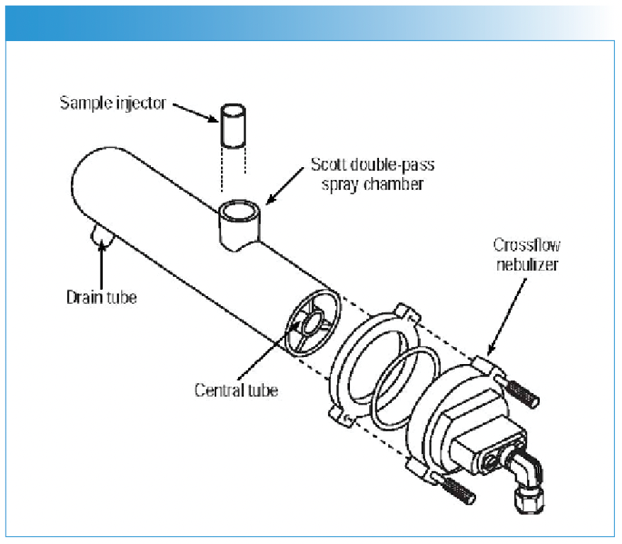
The Scott design is the most commonly used double-pass S/C, which selects the small droplets by directing the aerosol into a central tube. The larger droplets emerge from the tube, and by gravity, exit the spray chamber via a drain tube. The liquid in the drain tube is kept at positive pressure (usually by way of a loop), which forces the small droplets back between the outer wall and the central tube; they emerge from the spray chamber into the sample injector of the plasma torch. Scott double-pass spray chambers come in a variety of shapes, sizes, and materials, but are generally considered the most rugged design for routine use. Figure 4 shows a double-pass spray chamber (made of a polymer material) coupled to a cross-flow nebulizer.
FIGURE 4: A double-pass spray chamber coupled to a cross-flow nebulizer (courtesy of PerkinElmer Inc.).
Cyclonic S/C
The cyclonic spray chamber operates by centrifugal force, where droplets are discriminated according to their size by means of a vortex produced by the tangential flow of the sample aerosol and argon gas inside the chamber. Smaller droplets are carried with the gas stream into the ICP-MS, whereas the larger droplets impinge on the walls and fall out through the drain. It is generally accepted that a cyclonic spray chamber has a higher sampling efficiency, which for clean samples translates into higher sensitivity and lower detection limits. However, the droplet size distribution appears to be different from a double-pass design, and for certain types of samples can give slightly inferior precision. Beres and coworkers published a very useful study describing the capabilities of a cyclonic spray chamber (2). Figure 5 shows a cyclonic spray chamber with a concentric nebulizer.
FIGURE 5: Cyclonic spray chamber with a conventional concentric nebulizer, reference (2).
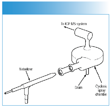
The most important maintenance task with regard to the spray chambers is to make sure that the drain is functioning properly. A malfunctioning or leaking drain can produce a change in the spray chamber backpressure, producing fluctuations in the analyte signal, resulting in erratic and imprecise data. Less frequent problems can result from degradation of O-rings between the spray chamber and sample injector of the plasma torch. Typical maintenance procedures regarding the spray chamber include the following:
- Make sure the drain tube fits tightly and there are no leaks.
- Ensure the waste solution is being pumped from the spray chamber into the drain properly.
- If a drain loop is being used, make sure the level of liquid in the drain tube is constant.
- Check O-ring or ball joint between spray chamber exit tube and torch sample injector—ensure the connection is snug.
- The spray chamber can be a source of contamination with some matrices/analytes, so flush thoroughly between samples.
- Empty spray chamber of liquid when instrument is not in use.
- Spray chamber and drain maintenance should be inspected every 1–2 weeks, depending on workload.
Plasma Torch and RF Generator
Not only is the plasma torch/sample injector exposed to the sample matrix and solvent, but they also have to sustain the analytical plasma at approximately 7000-10,000 K. This combination makes for a very hostile environment and therefore is an area of the system that requires regular inspection and maintenance. A plasma torch positioned in the RF coil is shown in Figure 6.
FIGURE 6: A plasma torch mounted in the torch box (courtesy of PerkinElmer Inc.).
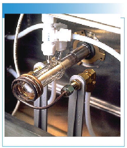
As a result, one of the main problems is staining and discoloration of the outer tube of the quartz torch because of heat and the corrosiveness of the liquid sample. If the problem is serious enough, it has the potential to cause electrical arcing. Another potential problem area is blockage of the sample injector due to matrix components in the sample. As the aerosol exits the sample injector, desolvation takes place, and the sample changes from small liquid droplets to minute solid particles prior to entering the base of the plasma. Unfortunately, with some sample matrices, these particles can deposit themselves on the tip of the sample injector over time, leading to possible clogging and drift. In fact, this can be a potentially serious problem when aspirating organic solvents, because carbon deposits can rapidly build up on the sample injector and cones unless a small amount of oxygen is added to the nebulizer gas flow. Some torches also use metal plates or shields to reduce the secondary discharge between the plasma and the interface. These are consumable items, because of the intense heat and the effect of the RF field on the shield. A shield in poor condition can affect instrument performance, so the user should always be aware of this and replace it when necessary.
Some useful maintenance tips with regard to the torch area include the following:
- Look for discoloration or deposits on the outer tube of the quartz torch. Remove material by soaking the torch in appropriate acid or solvent if required.
- Check torch for thermal deformation. A nonconcentric torch can cause loss of signal.
- Check sample injector for blockages. If the injector is demountable, remove the material by immersing it in an appropriate acid or solvent if required (if the torch is one piece, soak the entire torch in the acid).
- Ensure that the torch is positioned in the center of the load coil and at the correct distance from the interface cone when replacing the torch assembly.
- If the coil has been removed for any reason, make sure the gap between the turns is correct as per recommendations in the operator’s manual.
- Inspect any O-rings or ball joints for wear or corrosion. Replace if necessary.
- If a shield or plate is used to ground the coil, ensure it is always in good condition; otherwise, replace when necessary.
- The torch should be inspected every 1–2 weeks, depending on workload.
It’s also worth emphasizing that based on the design of the RF generator, the power amplifier (PA) tube is considered a consumable. There is no question that depending on the instrument’s age and the frequency of operation, the life of the PA tube could be seriously impacted. These components are not inexpensive and if one should unexpectedly fail, you will be faced with the cost of a service engineer’s time in addition to the cost of the tube, not to mention the downtime of the instrument.
Interface Region
As the name suggests, the interface is the region of the ICP mass spectrometer where the plasma discharge at atmospheric pressure is “coupled” to the mass spectrometer at 10−6 torr by way of two or three interface cones—a sampler and skimmer (and sometimes a hyper skimmer). This coupling of a high-temperature ionization source such as an ICP to the metallic interface of the mass spectrometer imposes demands on this region of the instrument that can be very challenging. When this is combined with matrix, solvent, and analyte ions together with particulates and neutral species being directed at high velocity at the interface cones, the result is an extremely harsh environment. The most common types of problems associated with the interface are blocking or corrosion of the sampler cone and, to a lesser extent, the skimmer cone. A schematic of the interface cones showing potential areas of blockage are shown in Figure 7.
FIGURE 7: A schematic of the interface cones showing potential areas of blockage.
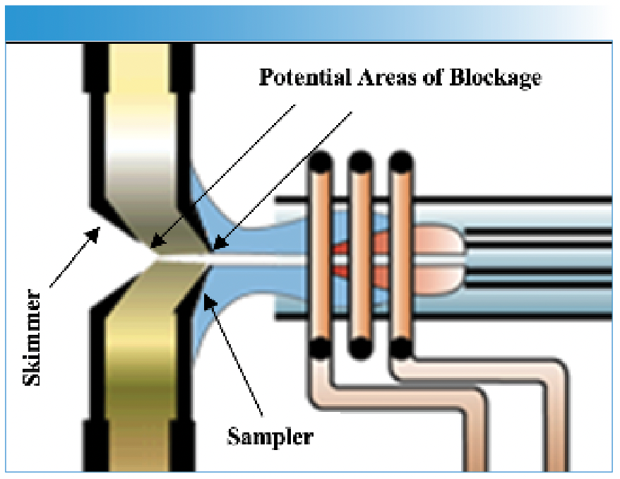
A blockage is not always obvious, because often the buildup of material on the cone or corrosion around the orifice can take a long time to reveal itself. For that reason, the sampler and skimmer interface cones have to be inspected and cleaned on a regular basis. The frequency will often depend on the types of samples being analyzed and also the design of the ICP mass spectrometer. Neufeld and coworkers wrote an excellent article on maintaining the cones and interface area to maximize productivity and uptime (3). For example, it is well documented that a secondary discharge at the interface can prematurely discolor and degrade the sampler cone, especially when complex matrices are being analyzed or if the instrument is being used for high sample throughput. Note: More information about the impact of a secondary discharge were described in an earlier chapter of the book.
Besides the cones, the metal interface housing itself is also exposed to the high-temperature plasma. Therefore, it usually needs to be cooled by water, either from a continuous water supply or a recirculating system, containing some kind of antifreeze or corrosion inhibitor (Note: Some of the new designs using proprietary RF technology are not water cooled). Recirculating systems are probably more widely used because the temperature of the interface can be controlled much better. There is no real routine maintenance involved with the interface housing, except maybe to check the quality of the coolant from time to time, to make sure there is no corrosion of the interface cooling system. If for any reason the interface gets too hot, there are usually built-in safety interlocks that will turn the plasma off. Some useful hints to prolong the lifetime of the interface and cones include the following:
- Check that both sampler and skimmer cone are clean and free of sample deposits. The typical frequency is weekly but will depend on sample type and workload.
- If necessary, remove and clean cones using the manufacturer’s recommendations. Typical approaches include immersion in a beaker of weak acid or detergent placed in a hot water or ultrasonic bath. Abrasion with fine wire wool or a coarse polishing compound has also been used.
- Never stick any wire into the orifice; it could do permanent damage.
- Nickel cones will degrade rapidly with harsh sample matrices. Use platinum cones for highly corrosive solutions and organic solvents.
- Periodically check cone orifice diameter and shape with a magnifying glass (10–20× magnification). An irregular-shaped orifice will affect instrument performance.
- Thoroughly dry cones before installing them back in the instrument because water/solvent could be pulled back into the mass spectrometer.
- Check coolant in recirculating system for signs of interface corrosion such as copper or aluminum salts (or predominant metal of interface).
Note: There are many different cone materials and inserts used nowadays, including nickel, platinum, copper, aluminum, and stainless steel.
Ion Optics
The ion optic system is usually positioned just behind or close to the skimmer cone to take advantage of the maximum number of ions entering the mass spectrometer. There are many different commercial designs and layouts, but they all have one attribute in common, and that is to transport the maximum number of analyte ions while allowing the minimum number of matrix ions, particulates and neutral species through to the mass analyzer.
The ion-focusing system is not traditionally thought of as a component that needs frequent inspection, but because of its proximity to the interface region, it can accumulate minute particulates and neutral species that over time can dislodge, find their way into the mass analyzer, and affect instrument performance. Signs of a dirty or contaminated ion optic system are poor stability or a need to gradually increase lens voltages over time. For that reason, no matter what design of ion optics is used; inspection and cleaning every 3–6 months (depending on workload and sample type) should be an integral part of a preventative maintenance plan. Some useful maintenance tips for the ion optics to ensure maximum ion transmission and good stability include the following:
- Look for sensitivity loss over time, especially in complex matrices.
- If sensitivity is still low after cleaning the sample introduction system, torch, and interface cones, it could indicate that the ion lens system is becoming dirty.
- Try retuning or re-optimizing the lens voltages.
- If voltages are significantly different (usually higher than previous settings), it probably means lens components are getting dirty.
- When the lens voltages become unacceptably high, the ion lens system will probably need replacing or cleaning. Use recommended procedures outlined in the operator’s manual.
- Depending on the design of the ion optics, some single-lens systems are considered consumables and are discarded after a period of time, whereas multicomponent lens systems are usually cleaned using abrasive papers or polishing compounds and rinsed with water and an organic solvent.
- When cleaning ion optics, make sure they are thoroughly dry because water or solvent could be sucked back into the mass spectrometer.
- Gloves are usually recommended when reinstalling an ion optic system because of the possibility of contamination.
- Do not forget to inspect or replace O-rings or seals when replacing ion optics.
- Depending on instrument workload, you should expect to see some deterioration in the performance of the ion lens system after 3–4 months of use. This is a good approximation of when it should be inspected and cleaned or replaced if necessary.
- With some instruments, you will need to break the vacuum to get to the ion optic region. Even though vacuum can be re-established very quickly, this should be a consideration when carrying out your own ion lens cleaning procedures.
Roughing Pumps
Typically, two roughing pumps are used in commercial instruments. One pump is used on the interface region, and the other is used as a backup to the turbomolecular pumps on the main vacuum chamber. They are usually oil-based rotary or diffusion pumps, where the oil needs to be changed on a regular basis, depending on the instrument usage. The oil in the interface pump will need changing more often than the one on the main vacuum chamber because it is pumping for a longer period. A good indication of when the oil needs to be changed is the color in the “viewing glass.” If it appears dark brown, there is a good chance that heat has degraded its lubricating properties, and it needs to be changed. With the roughing pump on the interface, the oil should be changed every 1–2 months, and with the main vacuum chamber pump, it should be changed every 3–6 months. These times are only approximations and will vary depending on the sample workload and the time the instrument is actually running. Some important tips when changing the roughing pump oil:
- Do not forget to turn the instrument and the vacuum off. If the oil is being changed from “cold,” it might be useful to run the instrument for 10–15 min beforehand to get the oil to flow better.
- Drain the oil into a suitable vessel; caution, the oil might be very hot if the instrument has been running all day.
- Fill the oil to the required level in the “viewing glass.”
- Check for any loose hose connections.
- Replace oil filter if necessary.
- Turn the instrument back on. Check for any oil leaks around filling cap and tighten if necessary.
Air Filters
Most of the electronic components, especially the ones in the RF generator, are air-cooled. Therefore, the air filters should be checked, cleaned, or replaced on a fairly regular basis. Although this is not carried out as routinely as the sample introduction system, a typical time frame to inspect the air filters is every 3–6 months, depending on the workload and instrument usage.
Other Components
It is also important to emphasize that other components of the ICP mass spectrometer have a finite lifetime and will need to be replaced or at least inspected from time to time. These components are not considered a part of the routine maintenance schedule, and usually require a service engineer (or at least an experienced user) to clean or to change them. The following area that might require cleaning from time to time.
Detector
Depending on the usage and levels of ion signals measured on a routine basis, the electron multiplier should last about 12 months. A sign of a failing detector is a rapid decrease in the “gain” setting despite attempts to increase the detector voltage. The lifetime of a detector can be increased by avoiding measurements at masses that produce extremely high ion signals, such as those associated with the argon gas, solvent or acid used to dissolve the sample (for example, hydrogen, oxygen, and nitrogen), or any mass associated with the matrix itself. It is important to emphasize that the detector should be replaced by an experienced person wearing gloves, to reduce the possibility of contamination from grease or organic/water vapor from the operator’s hands. It is advisable that a spare detector be purchased with the instrument.
Turbomolecular Pumps
Most of the instruments running today use two turbomolecular pumps to create the operating vacuum for the main mass analyzer/detector chamber and the ion optic region. However, some of the newer instruments use a single, twin-throated turbo pump. The lifetime of turbo pumps, in general, is dependent on a number of factors, including the pumping capacity of the pump (usually expressed as liters per second), the size (or volume) of the vacuum chamber to be pumped, the orifice diameter of the interface cones (in mm), and the time the instrument is running. Although some instruments still use the same turbo pumps after 5–10 years of operation, the normal lifetime of a pump in an instrument that has a reasonably high sample workload is on the order of 3–4 years. This is an approximation and will obviously vary depending on the make and design of the pump (especially the type of bearings used). As the turbomolecular pump is one of the most expensive components of an ICP-MS system, this should be factored into the overall running costs of the instrument over its operating lifetime.
It is worth pointing out that although the turbo pump is not generally included in routine maintenance, most instruments use a “Penning” (or similar) gauge to monitor the vacuum in the main chamber. Unfortunately, this gauge can become dirty over time and lose its ability to measure the correct pressure. The frequency of this is almost impossible to predict but is closely related to types and numbers of samples analyzed. A sudden drop in pressure or fluctuations in the signal are two of the most common indications of a dirty Penning gauge. When this happens, the gauge must be removed and cleaned. This should be performed by an experienced operator or service engineer because removing the gauge, cleaning it, maintaining the correct electrode geometry, and reinstalling it correctly into the instrument is a fairly complicated procedure. It is further complicated by the fact that a Penning gauge is operated at high voltage.
Mass Filter and Collision/Reaction Cell
Under normal circumstances, there is no need for the operator to be concerned about routine maintenance of the mass analyzer or collision/reaction cell. With modern turbomolecular pumping systems, it is highly unlikely there will be any pump contamination problems associated with the quadrupole, magnetic sector, or time-of-flight (TOF) mass analyzer. And very few sample matrix components ever make it into the mass spectrometer region, which dramatically reduces the frequency of routine maintenance tasks. This certainly was not the case with some of the early instruments that used oil-based diffusion pumps, because many researchers found that the quadrupole and pre-filters were contaminated by oil vapors from the pumps. Today, it is fairly common for turbomolecular-based mass analyzers to require no maintenance of the analyzer or the collision/reaction cell quadrupole rods over the lifetime of the instrument, other than an inspection carried out by a service engineer on an annual basis. However, in extreme cases, particularly with older instruments, removal and cleaning of the quadrupole assembly might be required to get acceptable peak resolution and abundance sensitivity performance.
Final Thoughts
The overriding message I would like to leave you with on this subject is that routine maintenance cannot be overemphasized in ICP-MS. Even though it might be considered a mundane and time-consuming chore, it can have a significant impact on the uptime of your instrument. Read the routine maintenance section of the operator’s manual and understand what is required. It is essential that time be scheduled on a weekly, monthly, and quarterly basis for preventative maintenance on your instrument. In addition, you should budget for an annual preventative maintenance contract under which the service engineer checks out all the important instrumental components and systems on a regular basis to make sure they are all working correctly. This might not be as critical if you work in an academic environment, where the instrument might be down for extended periods, but in my opinion, it is absolutely critical if you work in commercial laboratory, which is using the instrument to generate revenue. Although the cost of a PM contract might seem daunting, it typically includes one PM visit per year, and unlimited technical support, on-site repair visits and the price of replacement parts. You should check with your specific vendor/supplier for more detailed information.
There is no question that spending the time to keep your ICP mass spectrometer in good working order can mean the difference between owning an instrument whose performance could be slowly degrading without your knowledge or one that is always working in “peak” condition. And one of the ways to ensure this is to have a highly skilled operator, who knows how to keep the instrument optimized and working to its full potential.
And finally, I must give credit to the instrument designers and accessories suppliers in making today’s instrumentation extremely easy to maintain and keep clean. The technique is over 40 years old, and its commercial success has been built on acceptance by the analytical community for applying it to truly routine, real-world analysis. The only areas that need cleaning on a regular basis are the sample introduction system and interface cones, depending on usage and sample matrices being aspirated. And many of today’s instruments have alarms which can be set to remind the operator when it’s time for the few preventative maintenance tasks that are required, such as oil changes and tubing replacement. Some systems will even display how many hours various components have been used and when they might need attention. So even though routine maintenance is very important, instrument vendors and sampling accessories companies have put a great deal of time and effort into making this as straightforward and seamless as possible. Besides the major ICP-MS instrument vendors, here is a partial list of some of the companies that supply interface/torch/sample introduction/sampling accessories for the ICP-MS marketplace. Please contact them for more detailed support and troubleshooting information.
- Burgener Research
- CPI International
- Elemental Scientific Inc.
- Glass Expansion
- Mienhard Glass Products
- Precision Glass Blowing
- Savillex
- SCP Science
- Spectron Inc.
- Spex SamplePrep
- Teledyne Cetac Technologies
- Texas Scientific Products
Further Reading
(1) Neufeld, L. ICP-MS Interface Cones: Maintaining the Critical Interface Between the Mass Spectrometer and the Plasma Discharge to Optimize Performance and Maximize Instrument Productivity. Spectroscopy 2019, 34 (7), 12–17. https://www.spectroscopyonline.com/view/icp-ms-interface-cones-maintaining-critical-interface-between-mass-spectrometer-and-plasma-discharge
(2) Beres, S. A.; Bruckner, P. H.; Denoyer, E. R. Performance Evaluation of a Cyclonic Spray Chamber for ICP-MS. At. Spectrosc. 1994, 15(2), 96–99. https://url.us.m.mimecastprotect.com/s/Oq57CKrR2RiP9x6ouMf0C5cU1h?domain=scientificsolutions1.com
(3) Brennan, R.; Dulude, J.; Thomas, R. Approaches to Maximize Performance and Reduce the Frequency of Routine Maintenance in ICP-MS. Spectroscopy 2015, 30 (10), 12–25. https://www.spectroscopyonline.com/view/approaches-maximize-performance-and-reduce-frequency-routine-maintenance-icp-ms
Robert Thomas is the principal scientist of Scientific Solutions, a consulting company that serves the educational needs of the trace element user community. He has worked in the field of atomic and mass spectroscopy for more than 50 years, including 24 years for a manufacturer of atomic spectroscopic instrumentation. Rob also serves on the editorial advisory board of Technology Networks and recently accepted a position of Assistant Adjunct Professor at the University of North Dakota. He has written over 100 technical publications, including a 15-part tutorial series on ICP-MS, in addition to authoring 6 textbooks on the fundamental principles and applications of ICP-MS. His most recent book published in October 2023 is entitled “Practical Guide to ICP-MS and Other Atomic Spectroscopy Techniques: A Tutorial for Beginners.” Rob has an advanced degree in analytical chemistry from the University of Wales, UK, and is also a Fellow of the Royal Society of Chemistry (FRSC) and a Chartered Chemist (CChem). ●


LIBS Illuminates the Hidden Health Risks of Indoor Welding and Soldering
April 23rd 2025A new dual-spectroscopy approach reveals real-time pollution threats in indoor workspaces. Chinese researchers have pioneered the use of laser-induced breakdown spectroscopy (LIBS) and aerosol mass spectrometry to uncover and monitor harmful heavy metal and dust emissions from soldering and welding in real-time. These complementary tools offer a fast, accurate means to evaluate air quality threats in industrial and indoor environments—where people spend most of their time.
High-Speed Laser MS for Precise, Prep-Free Environmental Particle Tracking
April 21st 2025Scientists at Oak Ridge National Laboratory have demonstrated that a fast, laser-based mass spectrometry method—LA-ICP-TOF-MS—can accurately detect and identify airborne environmental particles, including toxic metal particles like ruthenium, without the need for complex sample preparation. The work offers a breakthrough in rapid, high-resolution analysis of environmental pollutants.