Effect of Sampling Optics on Raman Depth Profiling
Depth profiles of a laminar material have been measured on a confocal Raman microscope with a selection of microscope objectives. It is well known that the quality of the profiles will depend on the quality of the focus, which requires matching the objective’s engineered properties with the properties of the material, particularly the effects of the indices of refraction. Depth profile comparisons performed with a series of objectives will illustrate how better matching improves the spatial resolution and chemical speciation in the depth profile.
Since the introduction of the Raman microprobe in the mid-1970s, it has been said that the Raman microprobe is the ideal instrument for depth profiling transparent samples without cross-sectioning. Over the years, we have looked at different laminar materials with reasonable success. It was recognized, however, that the standard optics used on a Raman microscope are metallurgical, which means they are designed to image the surface of a flat opaque object. Anyone who has taken an optics course knows that when light penetrates a material, which by definition has an index of refraction greater than that of air (which is 1.0), the light will bend towards the normal of the interfacial boundary, and the degree of bending increases as the angle of incidence increases. This means that the optical parameters of the objective will not guarantee that all rays are focused at the same plane. Ironically, the degree of blurring will increase with the numerical aperture (NA) of the objective which is, in some ways, counterintuitive because as the NA increases, one expects the focus to become tighter. In thinking about this effect, it occurred to me that using an objective with a correction for an index greater than 1 might improve the situation. Such an objective could be an objective corrected to be used with a cover slip, or an immersion objective. This idea was explored in a short article where we showed the improvement in signal from a gaseous inclusion in a mineral when we compared the signal with a corrected objective vs. a metallurgical one (1). Subsequently, several laboratories have pursued this idea in more detail (2–4).
For a while, I have felt that it might be interesting to perform a depth profile on automobile windshield glass because it is made shatterproof by sandwiching a polymer layer between two layers of glass. The polymer that has the same index of refraction as the glass is selected for this application so one does not see multiple images in reflection or transmission. Well, I never got to an automobile junkyard to get a piece of this glass, but I began to consider the screen protectors used on cell phones as an alternative. Even though the thickness of these glass plates is of the order of a millimeter, they are quite flexible, suggesting that they might also be a sandwich structure similar to automobile windshield glass. So when I had to replace one of my screen protectors, I saved the old one for Raman analysis. I show in this column depth profiles taken with a 10x, 50x long working distance (LWD), 100x dry, 100x oil immersion, and 60x corrected for a cover slip. The numerical apertures for these objectives are 0.25, 0.50, 0.90, 1.4, and 0.9, respectively.
Results
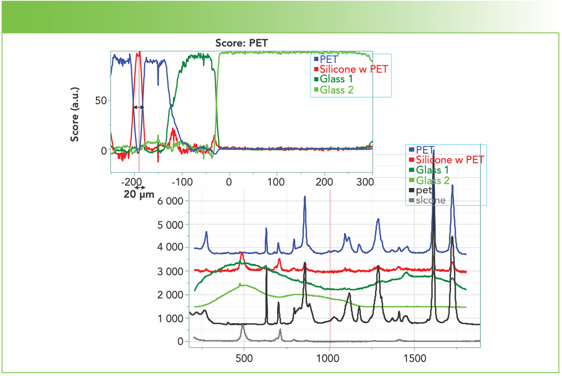
Because this column is meant to indicate the possibilities and limitations of depth profiling, I present the results of a low resolution cross-section measurement first. The sample is of the order of 0.5 mm thick, so it is not possible to probe the entire thickness with most objectives. When I started looking at the depth profiles with various objectives, I was confused because I did not know what was present. By measuring a cross-section, I was able to gain more knowledge to help me understand the depth profiles. Using a 5x objective, I was able to capture an image of the entire plate cross-section, and then map its composition without worrying about any loss of focus because such a low magnification objective is not subject to small changes in focus. I used the multiplicative curve resolution (MCR) algorithm to determine the factors and found that four factors accounted for the composition. The profile is shown in Figure 1. The top left part of Figure 1 shows the profile of the four factors shown in colors in the bottom right; the black and grey spectra represent reference spectra of polyethylene terephthalate (PET) black, and silicone (grey). Note that the silicone and PET spectra separate fairly well in the MCR factors.
FIGURE 1: Low magnification cross-sectional depth profiledepth profile (Z in micrometers) of the screen protector, with components identified as polyethylene terephthalate (PET), silicone (mixed with some PET), and two types of glass. Reference spectra of PET and silicone are shown at the bottom (Raman shift in cm-1 vs. Intensity).
That brings the discussion back to the depth profiles recorded with the objectives mentioned earlier. Note that only the 10x and 50x LWD objective enable measurements through the entire sample; the other objectives have working distances of the order of 100–200 μm. We used either classical least squares (CLS) or MCR to generate the factors and depth profiles. The factors are always plotted with the reference spectra in black or grey at the bottom to evaluate how well the spectral species are being separated in the profiles. Figure 2 shows the depth profile recorded with the 10x objective. The factors have been defined by CLS. Note how the layer definition is severely compromised. There is a complete absence of a layer of PET below the silicone layer and no evidence for a second glass spectral species even though the non-normalized score for the glass shows a dip near 500 μm. This is not unexpected because of the low spatial resolution of this objective. Clearly one would not try to get good depth information from thin films using the 10x objective.
FIGURE 2: Depth profile recorded with 10x objective. The top layer of PET film is seen in blue on the left, and the silicone is seen between the PET and the single glass species. The scores are not normalized here. Reference spectra are shown at the bottom (Raman shift in cm-1 vs. Intensity).
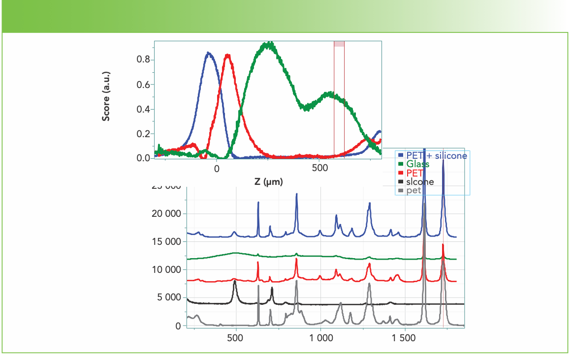
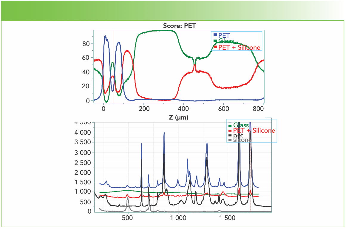
Figure 3 shows the depth profile with the 50x LWD objective. This objective has millimeters of working distance so it provides full access to the sample. Figure 3 shows results for 3 MCR factors, which include only one glass factor (adding a fourth factor to the calculation did not improve the result). Near the surface (Z = 0) the layer profiles do not look too bad; the silicone layer is of the order of 25 μm, but is apparently accompanied by glass, which is not correct. The second layer of the red silicone factor doesn’t make sense either because of the high glass content in that layer, so we know that this analysis cannot be accurate. This fact is also consistent with our knowledge of optics, which says that an objective with a high NA (in this case 0.5) that is not corrected for the index of the material will not provide good spatial selection. The dip in the scores at approximately 450 μm is presumably because of an air gap between the bottom of the sample, which is the glass side, and the glass microscope slide. Apparently, the glass in the screen protector is the same as that in the glass slide.
FIGURE 3: Depth profile of the screen protector measured with the 50x long working distance (LWD) objective. Reference spectra are shown at the bottom (Raman shift in cm-1 vs. Intensity).
Now we look at results from the 100x metallurgical lens, the 100x oil immersion lens, and then the 60x dry lens with corrections (Both of these last two lenses are meant to be used with a cover slip.).
Figure 4 shows the depth profile from the 100x metallurgical objective that has no corrections. Note that the 200 μm working distance limits how many layers can be measured. The two factors were generated with MCR, and they separate the PET and silicone components fairly well as can be seen in the top of Figure 4. The depth profiles are shown both with normalization (left) and without (right) scores. The significant drop in intensities of the non-normalized plot on the right is an indication of the lack of optical correction of the lens, but the width of the silicone layer is about 25 μm, which is only a bit larger than what was seen in cross-section.
FIGURE 4: Depth profile of the screen protector using the 100x metallurgical objective. These profiles have been generated with cursors around a band for PET and a band for silicone. Reference spectra are shown at the top (Raman shift in cm-1 vs. Intensity).
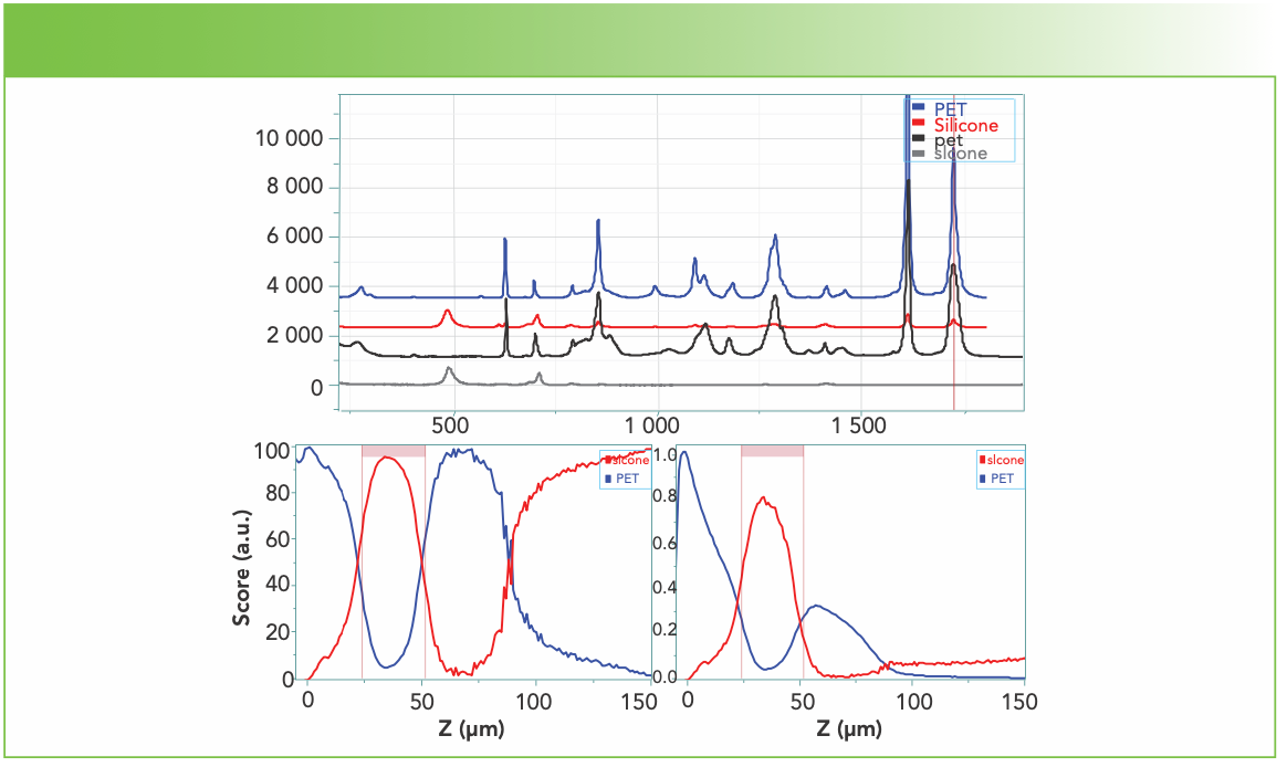
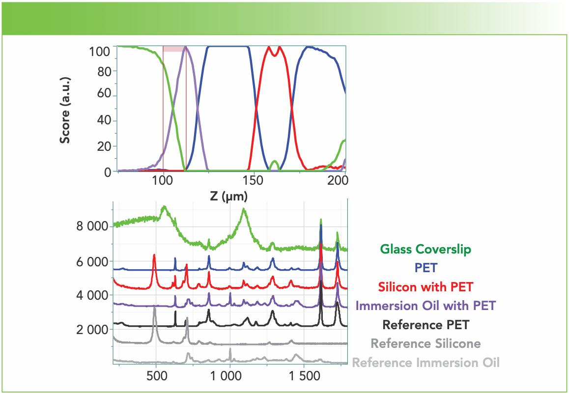
Figure 5 shows the results of the depth profile recorded with the oil immersion lens which has a 120 μm working distance. A 170-μm cover slip was placed above the sample, and oil was dropped both below and above the cover slip. The profile detects the presence of the immersion oil between the cover slip and the sample. It is curious that even with this lens, which is expected to produce good spatial resolution, the spectral components of PET appear in the other factors, especially that of silicone. But more puzzling is the apparent width of the silicone region, which we know is of the order of 20 μm. Because I do not know from where the 120 μm working distance is measured, I am assuming that the apparent large width of the silicone layer is because of the fact that the objective is in contact with the sample and the focal spot is not changing.
FIGURE 5: Depth profile of the screen protector using the 100x oil immersion objective. These profiles have been generated with cursors around bands for PET, silicone, cover slip, and immersion oil, and the scores are normalized. Reference spectra are shown at the bottom (Raman shift in cm-1 vs. Intensity).
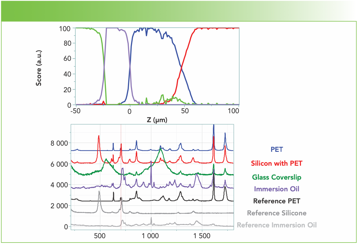
Figure 6 shows the results of the depth profile measurement recorded with the 60x objective corrected for a cover slip. A 170-μm thick cover slip was mounted, and the collar on the objective was set for 170 μm. This objective has a working distance of 200 μm. The factors were generated using CLS. This measurement was made after the measurement with the immersion oil, so the profile shows the presence of residual oil in a layer about 25 μm thick. The factor for PET is free of silicone, but the silicone factor has a rather larger contribution from PET. Note that the spectrum of PET is rather strong because of its aromatic character, and it does show up in the other factors. I remember hearing Neil Everall, one of the authors cited in the references, mention that when he was doing depth measurements, he was seeing evidence of a material even at depths where one would not predict to measure it. This story is not complete, so hopefully it can be sorted out because of the importance of making depth measurements by Raman spectroscopy.
FIGURE 6: Depth profile measured with 60x objective corrected for a cover slip. A 170 μm thick cover slip was mounted and the collar on the objective was set for 170 μm. This objective has a working distance of 200 μm. The factors were generated using classical least squares (CLS). Reference spectra are shown at the bottom (Raman shift in cm-1 vs. Intensity).
One measure of how well an objective will be able to differentiate layers will be the slope of the signal intensity when the focus enters each layer. For the four objectives (50x LWD, 100x metallurgical, 100x oil immersion, and 60x corrected-for-a-cover-slip), the distance between approximately 10 and 90% intensity is respectively 19, 23, 9, and 11 μm. The 50x LWD does better than the 100x metallurgical because its NA is smaller (0.5 vs. 0.9) and therefore introduces fewer aberrations. Both of the corrected lenses do quite well, and significantly better than the uncorrected lenses.
Summary
We have measured the composition of a cell phone screen protector, first in cross-section, and then by depth profiling using five microscope objectives with varying optical properties. The profile taken with the 10x objective failed to separate the spectral features or to detect some of the layers. The 50x LWD objective was able to probe the entire sample, but the scores were mixed and thus the results unreliable. The 100x metallurgical, uncorrected objective produced reasonably pure factors and profiles for the first three layers, but the non-normalized scores plot shows the effect of the lack of correction in that the intensity is dropping as the focal plane is moving further into the sample. Like the 100x metallurgical objective, the 100x oil-immersion objective that was used here has a very short working distance, on the order of 120 μm so only the top layers can be probed. The ability to separate layers is judged good from the slopes at the interfaces at -25 and 0 μm. The larger slopes at the interface between the top PET and the silicone at approximately 50 μm could indicate a chemical or physical mixing there, but because the top PET layer is meant to be peeled off, this seems unlikely. In my judgement, the 60x objective corrected for use with a cover slip has given the best results. The PET film on top is measuring 30 μm and the silicone layer is measuring 20 μm, but the residual immersion oil layer from the previous measurement is about 13 μm wide. However, the lack of effective separation of the spectra is still troubling.
The take-home message from this exercise is that without the correct objective, the ability to measure a laminar sample will be limited. In fact, in researching the working distances for the objectives that I used, I found that there are objectives with longer working distances that are corrected for a cover slip, with or without oil immersion. So for any project that requires knowledge about thin layers, and cross-sectioning is not a possibility, acquisition of an appropriate objective with a high quality Raman microscope can provide the information required.
References
(1) F. Adar, C. Naudin, A. Whitley and R. Bodnar, Appl. Spectrosc. 58(9) 1136–1137 (2004).
(2) N.J. Everall, Appl. Spectrosc. 54(6), 773–782 (2000).
(3) Y. Manuyama and W. Kanematsu, J. Appl. Phys. 110, 103017 (2011).
(4) N. Everall, J. Raman Spectroscopy 45, 133–138 (2014).
Fran Adar is the Principal Raman Applications Scientist for Horiba Scientific in Edison, New Jersey. Direct correspondence to: SpectroscopyEdit@mmhgroup.com.


New Study Reveals Insights into Phenol’s Behavior in Ice
April 16th 2025A new study published in Spectrochimica Acta Part A by Dominik Heger and colleagues at Masaryk University reveals that phenol's photophysical properties change significantly when frozen, potentially enabling its breakdown by sunlight in icy environments.
AI-Driven Raman Spectroscopy Paves the Way for Precision Cancer Immunotherapy
April 15th 2025Researchers are using AI-enabled Raman spectroscopy to enhance the development, administration, and response prediction of cancer immunotherapies. This innovative, label-free method provides detailed insights into tumor-immune microenvironments, aiming to optimize personalized immunotherapy and other treatment strategies and improve patient outcomes.
Nanometer-Scale Studies Using Tip Enhanced Raman Spectroscopy
February 8th 2013Volker Deckert, the winner of the 2013 Charles Mann Award, is advancing the use of tip enhanced Raman spectroscopy (TERS) to push the lateral resolution of vibrational spectroscopy well below the Abbe limit, to achieve single-molecule sensitivity. Because the tip can be moved with sub-nanometer precision, structural information with unmatched spatial resolution can be achieved without the need of specific labels.
AI Shakes Up Spectroscopy as New Tools Reveal the Secret Life of Molecules
April 14th 2025A leading-edge review led by researchers at Oak Ridge National Laboratory and MIT explores how artificial intelligence is revolutionizing the study of molecular vibrations and phonon dynamics. From infrared and Raman spectroscopy to neutron and X-ray scattering, AI is transforming how scientists interpret vibrational spectra and predict material behaviors.