Matching Filters to Fluorophores for In Vitro Diagnostics
Diagnostic instruments such as blood analyzers and flow cytometers utilize induced fluorescence to detect bio-factors of interest in a heterogeneous sample.
Gregory Fales, Edmund Optics Inc.
Many biological compounds can be tagged with fluorophores then induced to fluoresce to allow automatic detection and measurement using a vision system. Because the efficiency of absorption and emission are typically low, however, the fluorescence is essentially undetectable without filtering because reflected broadband illumination energy would be much greater than the emission signal. Filters reduce the reflected energy reaching the image sensor both by eliminating unnecessary illumination and blocking non-signal energy.
Fluorescent Microscopy
A fluorescent microscopy system typically utilizes three filters – excitation, emission, and dichroic – with an illumination source and an image sensor. An excitation filter resides in the optical path between the light source – often a high-intensity mercury lamp – and the sample, reducing illumination energy to only the wavelengths that the fluorophore will absorb. The dichroic filter, designed to reflect the excitation wavelengths and transmit the emission wavelengths, sits at a 45° angle in this path, reflecting the filtered illumination energy onto the sample. The sample fluoresces, and that signal passes straight through the dichroic and then through the emission filter to the image sensor. The dichroic and emission filter together prevent non-emission energy, such as simple reflections of the illumination energy, from reaching the sensor.
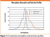
Choosing these filters begins with knowing the chosen fluorophore's unique spectral characteristics. The generalized spectral characteristics shown in Figure 1 illustrate the key parameters to determine. The wavelength at which the fluorophore absorbs energy most efficiently, or Peak Excitation λ (nm), and wavelength which it re-emits the maximum amount of absorbed energy, the Peak Emission λ (nm), are two of the key parameters. A third is the excitation range of the fluorophore, the boundaries of which are generally set at the wavelengths where the absorption efficiency is 50% of the peak. The remaining key parameter is the Intersection Wavelength, which occurs where the two spectral profiles cross.

Figure 1
Filters have corresponding parameters. The filter's Center Wavelength and bandwidth refer to the wavelength of maximum transmission and the range over which transmission remains at least 50% of peak. The filter's Minimum Transmission % tells how much of the energy at the center wavelength is guaranteed to pass through the filter. The filter's optical density is a measure of how completely it blocks energy outside of its bandwidth.
The excitation filter should have a center wavelength that matches as closely as possible the peak excitation of the fluorophore, with a bandwidth that encompasses the fluorophore's excitation range. The filter's minimum transmission will determine the amount of fluorescence attainable, so should be chosen to be as high as possible. A transmission greater than 85% is recommended, and filters with transmission >93% are ideal. Optical density should be at least 3 and ideally 6 or more to eliminate unnecessary noise in the image, caused by excitation wavelengths propagating through to the detector. This same set of parametric guidelines holds true for matching the emission filter to the fluorophore's emission spectrum.
Because the excitation and emission ranges overlap there remains the potential for reflected excitation energy to contaminate the fluorescence signal when using only these two filters. The dichroic filter will help eliminate this contamination. An ideal dichroic filter will have a sharp transition between its maximum reflection and maximum transmission wavelengths, with the transition occurring at or near the intersection wavelength to ensure minimal stray-light and a maximum signal-to-noise ratio in the fluorescent image. The dichroic should have a reflection >95% for the bandwidth of the excitation filter, and a transmission of >90% for the bandwidth of the emission filter.
Optical suppliers have stock filters pre-selected for use with many common fluorophores, eliminating the need for this analysis. Researchers seeking new alternatives, however, will need this understanding to maximize their ability to reliably detect faint emissions with experimental fluorophores.

Edmund Optics Inc.
101 East Gloucester Pike, Barrington, NJ 08007
tel. (800)363-1992 or (856)573-6250; fax: (856)573-6295
Website: www.edmundoptics.com

New Study Reveals Insights into Phenol’s Behavior in Ice
April 16th 2025A new study published in Spectrochimica Acta Part A by Dominik Heger and colleagues at Masaryk University reveals that phenol's photophysical properties change significantly when frozen, potentially enabling its breakdown by sunlight in icy environments.
Tracking Molecular Transport in Chromatographic Particles with Single-Molecule Fluorescence Imaging
May 18th 2012An interview with Justin Cooper, winner of a 2011 FACSS Innovation Award. Part of a new podcast series presented in collaboration with the Federation of Analytical Chemistry and Spectroscopy Societies (FACSS), in connection with SciX 2012 ? the Great Scientific Exchange, the North American conference (39th Annual) of FACSS.
Thermo Fisher Scientists Highlight the Latest Advances in Process Monitoring with Raman Spectroscopy
April 1st 2025In this exclusive Spectroscopy interview, John Richmond and Tom Dearing of Thermo Fisher Scientific discuss the company’s Raman technology and the latest trends for process monitoring across various applications.
A Seamless Trace Elemental Analysis Prescription for Quality Pharmaceuticals
March 31st 2025Quality assurance and quality control (QA/QC) are essential in pharmaceutical manufacturing to ensure compliance with standards like United States Pharmacopoeia <232> and ICH Q3D, as well as FDA regulations. Reliable and user-friendly testing solutions help QA/QC labs deliver precise trace elemental analyses while meeting throughput demands and data security requirements.