Maxwell's Equations, Part V
Here, we continue the discussion of electromagnetism and Maxwell's second equation.

This is the fifth installment in a series devoted to explaining Maxwell's equations, the four mathematical statements upon which the classical theory of electromagnetic fields — and light — is based. Previous installments can be found on Spectroscopy's website (www.spectroscopyonline.com/The+Baseline+Column). Maxwell's equations are expressed in the language of vector calculus, so a significant part of previous columns have been dedicated to explaining vector calculus, not spectroscopy. For better or worse, that's par for the course, and it's my job to explain it well — I trust readers will let me know if I fail! The old adage "the truth will set you free" might be better stated, for our purposes, as "math will set you free." And that's the truth.
In mid-1820, Danish physicist Hans Oersted discovered that a current in a wire can affect the magnetic needle of a compass. These experiments were quickly confirmed by François Arago and, more exhaustively, André Marie Ampère. Ampère's work, which defined a so-called "magnetic field" (labeled B in Figure 31), demonstrated that the effects generated were centered on the wire, perpendicular to the wire, and circularly symmetric about the wire. By convention, the vector component of the field had a direction given by the right hand rule: If the thumb of the right hand were pointing in the direction of the current, the curve of the fingers on the right hand gives the direction of the vector field.

Figure 31: The "shape" of a magnetic field about a wire with a current running through it.
Other careful experiments by Jean-Baptiste Biot and Félix Savart established that the strength of the magnetic field was directly related to the current I in the wire and inversely related to the radial distance from the wire r. Thus, we have

where "∝" means "proportional to". To make a proportionality an equality, we introduce a proportionality constant. However, because of the axial symmetry of the field, we typically include a factor of 2π (the radian angle of a circle) in the denominator of any arbitrary proportionality constant. As such, our new equation is

where the constant µ is our proportionality constant and is called the permeability of the medium the magnetic field is in. In a vacuum, the permeability is labeled µ0 and, because of how the units of B and I are defined, is equal to exactly 4π × 10-7 tesla-meters per ampere (T∙m/A).
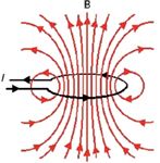
Figure 32: A wire loop generates a magnetic field B when a current I runs through the wire. In this case, the magnetic field is an axial field about the central axis of the loop.
Not long after the initial demonstrations, Ampère had another idea: curve the wire into a circle. Sure enough, inside the circle, the magnetic field increased in strength as the concentric circles of the magnetic field overlapped on the inside (Figure 32). Biot and Savart found that the magnetic field B created by the loop was related to the current I in the loop and the radius of the loop R:

Multiple loops can be joined in sequence to increase B, and in 1824–1825 English inventor William Sturgeon wrapped loops around a piece of iron, creating the first electromagnet. Even by then, Ampère had the thought that it was the current — that is, moving charges — that caused the magnetic field.
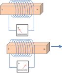
Figure 33: A magnet inside a coil of wire (top) does not generate a current. A magnet moving through a coil of wire (bottom) does generate a current.
Joseph Henry was an American scientist who eventually became the first secretary of the Smithsonian Institution. In 1830, he performed some experiments showing how a magnetic field can induce electricity and did not publish it. Because of this, he lost a larger place in scientific history when in 1831, Michael Faraday announced that a changing magnetic field could produce an electrical current. (Henry's work has not gone unnoticed, as the SI unit of inductance is named the henry.) Note that Faraday (followed by others) found that a changing magnetic field is required; a static, nonchanging magnetic field produces no current (Figure 33). This strongly suggests that an electric current I is related to a varying magnetic field, or

Actually, this is not far from the truth (which would then be another of Maxwell's equations if it were), but the more complete truth is expressed in a different, more applicable form.
Work in an Electrostatic Field
The simple physical definition of work (w) is force (F) times displacement (Δs):

This is fine for straight-line motion, but what about if the motion occurred on a curve (Figure 34 in two dimensions), with perhaps a varying force? Then calculating the work is not as straightforward, especially since force and displacement are both vectors. However, it can easily be justified that the work is the integral, from initial point to final point, of the dot product force vector F with the unit vector tangent to the curve, which we will label t:

Because of the dot product, only the force component in the direction of the tangent to the curve contributes to the work. That makes sense if you remember the definition of the dot product, a∙b = |a||b|cosΘ: if the force is parallel to the displacement, work is maximized (because the cosine of the angle between the two vectors is cos[0°] = 1) while if the force is perpendicular to the displacement, work is zero (because now the cosine is cos[90°] = 0).
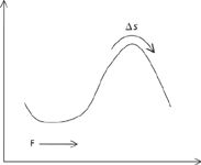
Figure 34: If the force F is not parallel to the displacement s (shown here as variable, but F can be variable too), then the work performed is not as straightforward to calculate.
Now consider two random points inside of an electrostatic field E (Figure 35). Keep in mind that we have defined E as static; that is, not moving or changing. Imagine that an electric particle with charge q were to travel from P1 to P2 and back again along the paths s1 and s2, as indicated. Because the force F on the particle is given by qE (this is from Coulomb's law), we have for an imagined two-step process:

Each integral covers one pathway, but eventually you end up where you started.
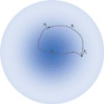
Figure 35: Two arbitrary points in an electric field. The relative strength of the field is indicated by the darkness of the color.
This last statement is a crucial one: Eventually you end up where you started. According to Coulomb's law, the only variable that the force or electric field between the two particles depends on is the radial distance, r. This further implies that the work, w, depends only on the radial distance between any two points in the electric field. Furthermore, this implies that if you start and end at the same point, as we are in our example, the overall work is zero because you are starting and stopping at the same radial point r. Thus, the equation above must be equal to zero:

Because we are starting and stopping at the same point, the combined paths s1 and s2 are termed a closed path. Notice too that, other than being closed, we have not imposed any requirement on the overall path s itself: It can be any path. We say that this integral, which must equal zero, is path-independent.
The symbol for an integral over a closed path is ∮. Thus, we have

We can divide by the constant q to get something slightly more simple:

This is one characteristic of an electrostatic field: the path-independent integral over any closed path in an electrostatic field is exactly zero.
The key word in the above statement is "any." You can select any random closed path in an electric field, and the integral of E∙t over that path is exactly zero. How can we generalize this for any closed path?
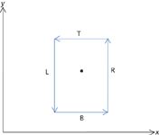
Figure 36: A closed, two-dimensional path around a point.
Let us start with a closed path in one plane, as shown by Figure 36. The complete closed path has four parts, labeled T, B, L, and R for top, bottom, left, and right, and it surrounds a point at some given coordinates (x, y, z). T and B are parallel to the x axis, while L and R are parallel to the y axis. The dimensions of the path are Δx by Δy (these will be useful shortly). Right now the area enclosed by the path is arbitrary, but later on we will want to shrink the closed path down so that the area goes to zero. Finally, the path is immersed in a three dimensional field F whose components are Fx, Fy, and Fz.
That is,

in terms of the three unit vectors i, j, and k in the x-, y-, and z-dimension, respectively.
Let us evaluate the work of each straight segment of the path separately, starting with path B. The work is

The tangent vector t is simply the unit vector i, since path B points along the positive x axis. When you take the dot product of i with F (see expression above), the result is simply Fx. (Can you verify this?) Finally, since the displacement s is along the x axis, ds is simply dx. Thus, we have

Although the value of Fx can vary as you go across path B — in fact, it is better labeled as Fx (x,y,z) — let us assume some average value of Fx as indicated by its value at a y-axis position of y – Δy/2, which is the y value ½ of the height of the box below the point in the center. Thus, we have

where we have replaced the infinitesimal dx with the finite Δx.
We can do the same for the work at the top of the box, which is path T. There are only two differences: first, the tangent vector is –i, because the path is moving in the negative direction, and second, the average value of Fx is judged at y + Δy/2, which is ½ of the height of the box above the center point. Hence, we can simply write

The sum of the work on the top and bottom are thus

Rearranging this so that it is in the form "top minus bottom" and factoring out the Δx, this becomes

Let us multiply this expression by 1, in the form of Δy/Δy. We now have

Recall that this work is actually a sum of two integrals involving, originally, the integrand F∙t. Reminding ourselves, this last expression can be written as

The term ΔxΔy is the area of the path, A. Dividing the area to the other side of the equation, we have

Suppose we take the limit of this expression as Δx = Δy = A → 0. What we would have is the amount of work done over any infinitesimal area defined by any random path — the only restriction is that the path is in the (x,y) plane. The equation above becomes

Looking at the second limit above and recalling our basic calculus, that limit defines a derivative with respect to y! But because Fx is a function of three variables, this is better defined as the partial derivative with respect to y. Thus, we have

Note the retention of the minus sign.
We can do the same thing for paths L and R. The analysis is exactly the same, only the variables that are affected change. What we get is (and you are welcome to verify the derivation)

Now, combine the two parts: The work done over an infinitesimally small closed path in the (x,y) plane is given by

Now isn't that a rather simple result?
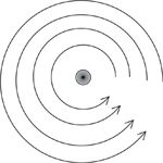
Figure 37: A two-dimensional sink with a film of water rotating counterclockwise as it goes down the drain.
Let us see an example of this result so we can understand what it means. Consider a two-dimensional sink, in the (x,y) plane, as diagrammed in Figure 37. A thin film of water is going down the central drain, and in this case it is spinning in a counter-clockwise direction at some constant angular velocity. The vector field for the velocity of the spinning water is

In terms of the angular velocity ω, this can be written as

(A conversion to polar coordinates was necessary to go to this second expression for v, in case you need to do the math yourself.) In this vector field, Fx = -ωy and Fy = ωx. To determine the limit of the work per unit area, we evaluate the expression

This is easy to evaluate:

Suppose we stand up a piece of cardboard on the sink, centered at the drain. Experience suggests to us that the cardboard piece will start to rotate, with the axis of rotation perpendicular to the flat sink. In this particular case, the axis of rotation will be in the z dimension, and to be consistent with the right hand rule, we submit that in this case the axis points in the positive z direction. If this axis is considered a vector, then the unit vector in this case is (positive) k. Thus, vectorially speaking, the infinitesimal work per unit area is actually

Thus, the closed loop in the (x,y) plane is related to a vector in the z direction. In the case of a vector field, the integral over the closed path is referred to as the circulation of the vector field.
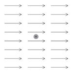
Figure 38: Water flowing in a two-dimensional sink with a constant left-to-right velocity.
As a counterexample, suppose water in our two-dimensional sink is flowing from left to right at a constant velocity, as shown in Figure 38. In this case, the vector function is

where K is a constant. If we put a piece of cardboard in this sink, centered on the drain, does the cardboard rotate? No, it doesn't. If we evaluate the partial-derivative expression from above (in this case, Fx = K and Fy = 0):

(Recall that the derivative of a constant is zero.) This answer implies that no rotation is induced by the closed loop.
Until Next Time
We've established some interesting ideas here, but we're out of room. In the next installment, we will continue this discussion and see how another one of Maxwell's equations arises.
David W. Ball is normally a professor of chemistry at Cleveland State University in Ohio. For a while, though, things will not be normal: starting in July 2011 and for the commencing academic year, David will be serving as Distinguished Visiting Professor at the United States Air Force Academy in Colorado Springs, Colorado, where he will be teaching chemistry to Air Force cadets. He still, however, has two books on spectroscopy available through SPIE Press, and just recently published two new textbooks with Flat World Knowledge. Despite his relocation, he still can be contacted at And finally, while at USAFA he will still be working on this series, destined to become another book at an SPIE Press web page near you. d.ball@csuohio.edu.

David W. Ball
Reference
(1) D.W. Ball, Spectros. 26(9), 18–27 (2011).
(2) Other references: In writing this series, I have been strongly influenced by the following works:
- H.M. Schey, Div, Grad, Curl, and All That: An Informal Text on Vec-tor Calculus (W.W. Norton and Company, New York, New York, 2005). This is a wonderful text for someone needing the fundamen- tals of vector calculus. It is engag- ing and light-hearted, two adjec- tives that you would swear would never be used in a description of vector calculus!
- D. Fleisch. A Student's Guide to Maxwell's Equations (Cambridge University Press, Cambridge, UK, 2008). This very approachable book takes the tactic of parsing each equation and explaining what each part means; very useful in understanding the fundamentals of Maxwell's equations.

Best of the Week: AI and IoT for Pollution Monitoring, High Speed Laser MS
April 25th 2025Top articles published this week include a preview of our upcoming content series for National Space Day, a news story about air quality monitoring, and an announcement from Metrohm about their new Midwest office.
LIBS Illuminates the Hidden Health Risks of Indoor Welding and Soldering
April 23rd 2025A new dual-spectroscopy approach reveals real-time pollution threats in indoor workspaces. Chinese researchers have pioneered the use of laser-induced breakdown spectroscopy (LIBS) and aerosol mass spectrometry to uncover and monitor harmful heavy metal and dust emissions from soldering and welding in real-time. These complementary tools offer a fast, accurate means to evaluate air quality threats in industrial and indoor environments—where people spend most of their time.