Spectrometers for Elemental Spectrochemical Analysis, Part II: X-Ray Fluorescence Spectrometers
The basic modules of spectrometer systems were discussed in Part 1 of this series, and here, the authors focus on the X-ray excitation sources.
Roentgen's 1895 discovery of X-rays was followed quickly by Becquerel's discovery of radioactivity in 1896. Both provide useful excitation in the X-ray region of the electromagnetic (EM) spectrum.
In 1906, Barkla discovered that each element had its own characteristic X-ray spectrum. Then, in 1913, Moseley discovered the relationship between the wavelength of characteristic lines and atomic number. These results paved the way for spectrochemical analysis by X-ray excitation.
The two primary ways to produce the X-rays required for spectrochemical analysis are the X-ray tube and the radioisotope source. American physicist William David Coolidge (1873–1975) introduced the hot filament, high-vacuum X-ray tube in 1913. Subsequent years produced many improvements, such as the water-cooled tube and the rotating anode X-ray tube. Research with radioisotope sources began in the early decades of the 20th century. However, such sources did not become readily available on a commercial basis until the 1950s. Further historical information is available (2–4).
The X-ray excitation source provides enough energy to eject electrons from the innermost electron shells of atoms. The excited atoms return to their ground state through a series of one or more steps by reacquiring electrons and, like optical emission, giving off characteristic "light," in this case in the X-ray part of the EM spectrum.
X-Ray Tube Excitation
An X-ray tube is a vacuum tube that provides a source of electrons and a means of accelerating them to very high speeds. It consists of a thin piece of wire — the cathode — and a metal target for the electrons, the anode, as shown in Figure 1. A small voltage (6 V, for example) applied to the cathode is sufficient to cause electrons to leave the surface of this wire. Now if a large positive voltage is applied to the anode, the negatively charged electrons will be accelerated towards it. This accelerating voltage is generally on the order of 30 to 100 kV.
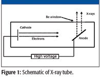
Figure 1
The material used for the anode of the X-ray tube is an important consideration as it determines the fluorescence component of the emitted X-rays. Rhodium is a common anode material, although molybdenum, palladium, silver, tungsten, and occasionally other elements are also used.
The X-ray tube produces excitation of two forms: a continuum "bremsstrahlung" or "braking radiation" as the electrons decelerate upon hitting the target, and X-rays characteristic of the anode material.
Applying the law of conservation of energy to the X-ray tube, we have electrical energy going in and X-rays coming out. The electrical energy is given by the product of the excitation voltage (V) and the charge (Q). If we consider only one electron, then Q is the charge of the electron (Qe). The energy of the photon emitted is given by Planck's law, E = hν, or expressed in terms of wavelength, E = hc/λ. Therefore we can write,

In this equation the constants are Qe = 1.602 × 10⁻¹⁹ C, h = 6.626 × 10⁻³⁴ J s, and c = 3.0 × 10⁸ m/s. Therefore,


This expression is known as the Duane-Hunt Law (1915) and allows the calculation of the minimum tube voltage required to produce an X-ray of wavelength λ. Or conversely, the minimum wavelength produced by a given tube voltage. Because the tube voltage is generally expressed in kilovolts (= 103 V) and the wavelength of the photon in nanometers (= 10-9 m), this can be written as
Why does this express the "minimum" wavelength, rather than just the wavelength of emitted X-ray photons? The simple answer is because electrical energy of some of the incoming electrons may be "lost" to heat the anode. A more complete answer includes the energy "loss" due to absorption of the X-rays in the various atomic layers of the anode material.
The electrons striking the anode may also cause the excitation of the X-rays characteristic of the anode material by ejecting inner shell electrons. Therefore, the overall emission spectrum of an X-ray tube will be the sum of its continuum and fluorescence components, as shown in Figure 2. The peaks at 22 and 25 keV are due to the silver anode (Ag Kα and Kβ).
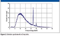
Figure 2
The intensity (I) of the characteristic spectral lines of the elements excited by an X-ray tube operating at a voltage (V) and current (i) is has been determined experimentally to be,

where A is a constant, VB is the voltage to necessary to overcome the binding energy and the exponent (n) has a value between 1.5 and 2. We can (approximately) translate this into English as follows: The intensity of a characteristic spectral line of an element is proportional to the tube current (i) and the difference between the tube voltage and the element's K-shell (or L-shell) electron binding energy. This is a useful relationship for spectrochemical analysis by XRF: The greater the tube voltage and current, the greater the intensity of the spectral line of interest.
However equation 4 is not a straight proportionality due to the exponent. "The rapid increase in intensity predicted . . . does not materialize when V exceeds three or four times the critical voltage . . ." (5). The fact that this equation breaks down after the tube voltage exceeds about three to four times the binding energy is also a very useful bit of data for the spectrochemist. In fact, it is why we use multiple excitation conditions in X-ray fluorescence (XRF). For example, if we consider just the K-lines of the analyte, use a high voltage and low current for the higher atomic number elements and a lower voltage and higher current for those with lower atomic number.
Radioisotope Excitation
Radioisotope excitation sources have traditionally been used primarily in portable and handheld XRF instrumentation. However, the recent development of miniature X-ray tubes has prompted a decline in their use. A few comments on this excitation source are provided here.
Typical radioisotopes used in handheld and portable X-ray fluorescence instrumentation include 109Cd, 241Am, and 55Fe. The half-lives of these isotopes are:
- Cadmium-109.......... 1.27 years
- Americium-241......... 432 years
- Iron-55........................2.73 years
The cadmium-109 source emits X-rays with energies of 22 and 25 keV as it decays to silver-109 in a nuclear process known as electron capture. In addition, a small portion (3.8%) of its energy is emitted at 88 keV. This isotope has a half-life of 1.24 years, meaning that after this time the source activity is half its original value.
The americium-241 radioisotope is a source of 59.5 keV X-rays, allowing for the excitation of higher atomic number elements. This source also can provide excitation at 13.95 and 17.7 keV, which enables efficient excitation of the lower atomic number elements. This isotope has a half-life of 432 years and therefore "never" requires replacement. The americium-241 radioisotope decays as follows: 241Am → 237Np + 4He + 5.6 MeV. The neptunium-237 nucleus then decays into a lower energy state by emitting a 59.5 keV X-ray.
The iron-55 source emits 5.9 keV X-rays as it decays to manganese-55 in the electron capture process noted previously.
Absorption of X-Rays by Matter
The primary radiation as emitted by the excitation source is used to bombard the sample constituent atoms, removing electrons from their inner shells and thus giving rise to the characteristic secondary spectra. The absorption of X-rays by matter follows the Beer-Lambert law and is important for an understanding of the analytical performance of XRF spectrometers. However, as this was the subject of a previous tutorial (6), it will not be further discussed here.
X-Ray Spectrometer Systems
XRF instruments fall into two categories, wavelength dispersive (WDXRF) and energy dispersive (EDXRF). Wavelength-dispersive instruments have a long history of almost 100 years while the newer energy dispersive spectrometers are about 40 years old (2–4).
In WDXRF, a high-resolution detector is not required as the resolution is provided by the crystal dispersing element. Therefore, a low resolution detector capable of high count rates such as a proportional counter can be used (7).
For the wavelength dispersive X-ray systems, a crystal is used to disperse light to the detector following Bragg's law so that it functions as an X-ray grating (1). It relies on the crystal to separate the X-rays into their component wavelengths, and has excellent resolution, approximately 3 eV.
The dispersing crystals may be made from any number of different materials. Early spectrometers used topaz (aluminum silicate), quartz (SiO2), and beryl (beryllium-aluminum silicate). Common crystals today include lithium fluoride (LiF), pentaerythritol, thallium acid phthalate, germanium, and indium antimonide (InSb) (8). Also, there are synthetic multilayer structures used as diffraction elements for long wavelength X-rays.
In a basic WDXRF spectrometer, the sample is exposed to X-rays and the fluorescent X-rays pass through a collimator and strike the crystal. Those X-rays meeting the Bragg requirement will be reflected and pass though a second collimator to reach the detector (Figure 3).
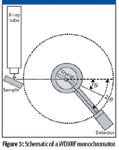
Figure 3
WDXRF spectrometers come in two basic instrument designs, the monochromator and the polychromator. In the monochromator design for sequential measurements, both the crystal and single detector are rotated along a given path to measure the various wavelengths (Figure 3). It must be noted that to satisfy Bragg's equation, the detector displacement angle must be twice that of the crystal, as shown in Figure 3. The polychromator is actually a collection of many monochromators with each set for a particular spectral line. This is useful for the simultaneous measurement of many spectral lines.
In EDXRF systems, the X-rays are not dispersed into their component energies before entering the detector; the separation is performed in the detector itself. The silicon PIN diodes and the newer silicon drift detectors are now used (1). Older instruments used sodium iodide (NaI), "Cad-Tel" (CdTe), mercuric iodide, lithium-drifted silicon (Si[Li]), and high purity Ge detectors (7).
The best quoted resolution for EDXRF is less than 130 eV, although most currently manufactured instruments typically have anywhere between about 160- and 220-eV resolution. The resolution of any detector, but especially those used in EDXRF, is important when the sample analytes have their characteristic X-ray energies in close proximity. (This is not generally an issue in WDXRF since the resolution is easily an order of magnitude better than currently achievable with semiconductor diodes.)
To compare detector resolution, the procedure has been standardized: Measure the 5.9-keV Ka peak of manganese and determine the full width at half maximum (FWHM) of this peak. This is illustrated in Figure 4, which shows a resolution for an older Si PIN detector of approximately 330 eV.
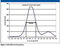
Figure 4
Some Analytical Considerations
A comparison of the analytical capabilities of these two XRF systems is certainly of interest to analytical chemists. A short summary is provided below.
Precision:
- WDXRF less than 0.1% relative standard deviation (RSD).
- EDXRF about 0.2% RSD.
- These RSDs are based upon concentrations well above the detection limits and will vary with the analyte, measurement time and specific excitation conditions.
- Note: %RSD = (1σ × 100)/Mean.
Limits of Detection (LODs) in a light matrix:
- WDXRF between about 0.1 and 2 ppm (mg/kg).
- EDXRF between about 0.1 and 50 ppm.
- These (3σ) detection limits will vary according to excitation conditions, atomic number and measurement time.
- Detection limits for light elements (for example, Z < 20) will generally be worse than the maximum noted in the ranges earlier.
Elemental Range:
- WDXRF from B to U.
- EDXRF from Na to U.
Measurement Time:
- Simultaneous WDXRF instruments (polychromators) will be much faster than the scanning WDXRF monochromator.
- EDXRF systems will have measurement times comparable to those of WDXRF polychromators instruments.
Price-to-Performance Ratio:
Generally WDXRF systems are significantly more expensive than EDXRF spectrometers.
Special Topics
We will now address briefly some special topics of interest in this final section: handheld XRF, polarized X-ray excitation, and the silicon drift detector.
Handheld XRF: Portable X-ray spectrometers have been around for many years (9). Today, these instruments are handheld, not just portable, and use EDXRF technology. Until the introduction of the miniature X-ray tube (ca. 2000), all handheld XRF analyzers used radioisotope excitation. The first units with miniature X-ray tube excitation were introduced in 2002.
These handheld instruments are of considerable interest to analytical chemists and not only as a "screening tool." Currently available handheld XRF spectrometers have the ability to provide laboratory quality analyses in the field. Figure 5 shows an example of the accuracy attainable with handheld XRF in the determination of titanium in various alloys (10). This provides a serious advantage to analysts. The time and money saved by no longer sending samples to a central laboratory is surely significant.
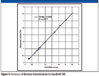
Figure 5
Polarized X-Ray Excitation: Direct excitation of the sample by the primary X-Ray radiation is used in both WDXRF as well as in conventional EDXRF. These techniques present a high spectral background due to the scattered radiation produced by the primary beam when hitting the sample (Compton effect). The lighter the matrix material, the higher is the scattered background. This high background noise is responsible for the loss of sensitivity and worse LOD values, especially for the light elements.
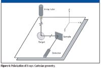
Figure 6
The use of a "polarizing filter" placed as a target for the primary X-ray tube radiation can significantly reduce the scattered background noise, thus enhancing the signal-to-background ratio (SBR) at the detector. A special optical geometry is required, where all the basic components of the instrument, that is, the tube, the polarizer, the sample and the detector are placed at angles of 90° with respect to each other, in an arrangement called "Cartesian geometry" (11). Spectrometers using this polarized X-ray beam technology were developed in the early 1990s.
As is often the case with technological innovations, the use of polarized X-ray excitation provides both advantages and disadvantages. The background reduction means better limits of detection. However it should also be noted that the reduction of primary beam intensity means longer integration times are required.
Silicon Drift Detector: The silicon drift detector was introduced in the 1990s. It provides very high count rates and improved resolution over the silicon PIN detector. They have been used successfully in laboratory EDXRF spectrometers and, more recently, in handheld XRF analyzers. Some currently available handheld spectrometers can successfully quantify the light elements (Mg, Al, Si) in air without the need for a vacuum or helium purge. Table I shows approximate LODs for Mg and Si in aluminum alloys for a 60-s measurement time using a handheld XRF spectrometer with a silicon drift detector in air.
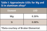
Table I: Approximate LODs for Mg and Si in aluminum alloys*
A recent article in this journal (12) provides details of silicon drift detectors as a detector in scanning electron microscopy.
Summary
A discussion of both the X-ray tube and radioisotope excitation sources has been provided. Both wavelength and energy-dispersive systems are addressed and some analytical comparisons provided. Also, some special topics of interest have been addressed. This short tutorial is meant to provide only an introduction. In addition to the references provided, there are several excellent introductions to XRF, some available on the web. Like arc/spark spectrometry, XRF is a mature technology. Yet both continue to evolve in response to industry pressure for better instrument performance.
Disclaimer
The use of illustrations or information from any instrumentation manufacturer does not imply any endorsement of this product. Nor does the instrumentation manufacturer provide implicit agreement with the material as presented in this article.
Carlos Augusto Coutinho, a retired Senior Researcher at Usiminas Steelworks R&D Analytical Division, is presently a consultant in Brazil. As a hobby, he enjoys reading subjects related to anthropology and playing the piano. E-mail: cacoutinho@task.com.br.
Volker Thomsen, a physicist by training, has some 30 years of experience in elemental spectrochemical analysis (OES and XRF). He is currently a consultant in this area from his home in Atibaia, São Paulo, Brazil. His other interests include mineralogy and history of science. Occasionally, he still plays the blues harmonica. He can be reached at vbet1951@uol.com.br.
References
(1) V. Thomsen, Spectroscopy 25(1), 46–54 (2010).
(2) E.P. Bertin, Introduction to X-Ray Spectrometric Analysis (Plenum Press, New York, 1978).
(3) V. Thomsen, Spectroscopy 21(10), 32–42 (2006).
(4) R.W. Ryon, X-Ray Spectrom. 30, 361–372 (2001).
(5) R. Tertian and F. Claisse, Principles of Quantitative X-Ray Fluorescence Analysis (Heyden, London, UK, 1982).
(6) V. Thomsen, D. Schatzlein, and D. Mercuro, Spectroscopy 20(9), 22–25 (2005).
(7) G.F. Knoll, Radiation Detection and Measurement, 3rd Ed. (John Wiley & Sons, Hoboken, New Jersey, 2000).
(8) J.A. Helsen and A. Kuczumow, "Wavelength-Dispersive X-Ray Fluorescence" in Handbook of X-Ray Spectrometry, Van Grieken and Markowicz, Eds., 2nd ed. (Marcel Dekker, Inc., New York, 2002).
(9) S. Piorek, Field Anal. Chem. Technol. 1(6), 317–329 (1997).
(10) V. Thomsen and D. Schatzlein, J. Process Anal. Chem. Aug. 2004.]
(11) J. Heckel and R.W. Ryon, "Polarized Beam X-ray Fluorescence Analysis" in Handbook of X-Ray Spectrometry, Van Grieken and Markowicz, Eds., 2nd ed. (Marcel Dekker, Inc., New York, 2002).
(12) D.E. Newbury, Spectroscopy 24(7), 32–43 (2009).
LIBS Illuminates the Hidden Health Risks of Indoor Welding and Soldering
April 23rd 2025A new dual-spectroscopy approach reveals real-time pollution threats in indoor workspaces. Chinese researchers have pioneered the use of laser-induced breakdown spectroscopy (LIBS) and aerosol mass spectrometry to uncover and monitor harmful heavy metal and dust emissions from soldering and welding in real-time. These complementary tools offer a fast, accurate means to evaluate air quality threats in industrial and indoor environments—where people spend most of their time.
NIR Spectroscopy Explored as Sustainable Approach to Detecting Bovine Mastitis
April 23rd 2025A new study published in Applied Food Research demonstrates that near-infrared spectroscopy (NIRS) can effectively detect subclinical bovine mastitis in milk, offering a fast, non-invasive method to guide targeted antibiotic treatment and support sustainable dairy practices.