Understanding and Interpreting the GAMP 5 Life Cycle Models for Software
Bob McDowall looks at the different life cycle models that apply in the laboratory to GAMP software categories 3, 4, and 5.

In the June installment of "Focus on Quality" (1), we looked at the classification of software from the new GAMP guide version 5 (2). This was the classification of software into four, or if you preferred my version, five different categories. Now I would like to spend time in this column looking at the life cycles that are applicable to software in categories 3, 4, and 5.

R.D. McDowall
The reason is that the life cycle associated with each category of software is the main way of determining the amount of validation work you will need to undertake. But the key to this approach is an honest and accurate appraisal of the software category. If this is mistakenly or deliberately underestimated — that is, if a category 4 application is classified as category 3 software — then a laboratory has a compliance hole that will cost more in time, effort, and reputation to sort out later than doing the work correctly in the first place. However, before we begin, let's recap what these three categories of software are in case you did not read the thrilling June installment or simply forgot what I wrote.
Software Categories 3, 4, and 5: A Quick Reprise
GAMP version 5 (2) has defined these three software categories as follows:
- Category 3: Nonconfigured Products
Off-the-shelf products that cannot be changed to match the business processes but this category also can include configurable software products but where only the default configuration is used.
- Category 4: Configured Products
Configured software products provide standard interfaces and functions that enable configuration of the application to meet user-specific business processes. However, configuration using a vendor-supplied scripting language should be handled as custom components (category 5).
- Category 5: Custom Applications
These applications are developed to meet the specific needs of a regulated company. This definition implicitly includes spreadsheet macros written using visual basic for applications (VBA) and LIMS language customizations. It also will include macros written for some spectroscopy software as short cuts for performing a series of tasks. Note that this is the highest risk software, as there is the greatest likelihood of functional omissions, bugs, and errors in the software, and therefore, the life cycle model used needs to have sufficient controls to ensure that it is properly specified, designed, built, and tested before release.
GAMP 5 notes that these categories are not silos of software but a continuum: There might be elements of a higher or lower category depending how the software is used and/or configured or customized.
Why Is a System Life Cycle Model Important?
A software application or a computerized system does not suddenly materialize out of thin air. Each one needs to be planned and implemented. Therefore, the use of a system life cycle is important as it provides a plan to use as a basis for the implementation or building of a computerized system.
Note the words:
- Plan: A plan is a blue print or road map for carrying out a task. It will outline the stages or phases that need to be gone through so that the system will be built correctly and function as required.
- Basis: Plans can be changed to fit the system that is being implemented or developed and you should accept that there is no one-size-fits-all approach. A specific system can have more, the same, or fewer needs than the standard life cycle model will provide and therefore, adaptation of the plan might be needed to accommodate them.
Therefore, the key requirement of any life cycle model used is that it should be meaningful and applicable to the system that you are building or implementing. If it is not, then you have problems.
Using V Life Cycle Models
Most of the life cycles used for validation of computer systems in the pharmaceutical and healthcare industries are based upon a V model. For the more observant of readers, this is because the phases form a V. The basic principle of a V model is shown in Figure 1.
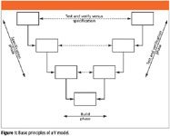
Figure 1
There are four basic principles of V models that you will need to understand as we go through the discussion of the variations of a theme in the rest of this column.
- The life cycle starts on the left-hand side with the specification phases, which will define what the system will do and how it will be built. Documentation of the various specifications means that you have to write down what you want, which most people do not do until after the event.
- From the specification phase, there should be enough information to build the system, which occurs at the base of the V. This is where the software is programmed and informally tested by the developer or programmer.
- The testing and verification of the built system occurs on the right-hand side of the V. Testing is exercising the software against a specification and verification is confirmation that a requirement is met outside of the software by the writing of a procedure or the installation of a component.
- Typically, there is a symmetry in the V as the testing and verification of the system is against the specification on the same level, so there is more detailed testing at the lower levels of the V (white box testing focused on the inputs and outputs of the modules of software) and higher level testing at the top of the V (black box testing looking at the overall functions of the system).
The model implies a stately progression from specification, build, and test/verify. What is never shown or described in the textbooks and guidance documents but happens in real life is the scenic trip through the life cycle. The user requirements specification is rushed or in many cases is not written at all and then the wrong system is selected or built and the rest of the life cycle is a scrabble to recover a degree of credibility of the system and demonstrate to the boss that it sort of works. As an alternative trip through the life cycle, after placing custom software in front of the users, the feedback "This is great but we don't work this way" can mean back to the drawing board. Spend time on the specification or you will pay much more in the future.
Also, the V model in Figure 1 does not describe who does which portion of the life cycle phases. For some systems (for example, a spreadsheet), a spectroscopist in a laboratory could undertake the whole work themselves (of course under the watchful gaze of those helpful people in quality assurance who will be riding shotgun on the work). Alternatively, if you buy commercial software, part of the V model will be your responsibility and the rest will be performed by the vendor and together, the two parts make the whole. Having understood the basics of the life cycle, at this point, enter stage left, the original GAMP V model.
In the Beginning: The Original GAMP Life Cycle Model
In the beginning was the GAMP life cycle V model. It is important to realize that since its inception in the early 1990s, the GAMP guide has always had a life cycle model, shown in Figure 2. However, the problem, from the laboratory perspective, is that the original aim of the GAMP guide was to control suppliers of manufacturing production equipment to the pharmaceutical industry. Thus, the V model used in the first four versions of the GAMP guide from 1994 to early 2008 was intended primarily for manufacturing equipment (3). For its original intention, this V model works well for manufacturing equipment and systems that consist mainly of equipment with some computer control elements that are supplied by engineering companies. Many of these systems have a basic equipment configuration that is then customized to fit an individual facility or manufacturing line.
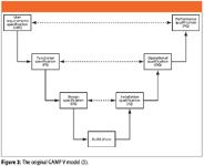
Figure 2
The left-hand side of the life cycle deals with the specification of the system: the users write the user requirements specification and then the selected vendor, in conjunction with the users, writes the functional specification and the design specification. The system is built at the bottom of the V, typically at the vendor's site, and tests called factory acceptance tests (FAT) can be conducted on the system to see if it works correctly, and the installation qualification (IQ) could be preceded by site acceptance tests (SAT).
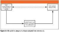
Figure 3
However, there are many problems when this is adapted for computerized systems, the primary one being it does not fit! So in many regulated organizations, the adoption of a life cycle model for manufacturing equipment caused problems when applied to computerized systems and laboratory systems. Let us look at the problems:
- The assumption with this model is that the system is custom and not off the shelf, in contrast to most computerized systems used in the laboratory that are commercially available and are used as is or configured.
- The left-hand side of the V dealing with the specification does not include any configuration of the category 4 software to match the business process.
- It implies that all stages of the model need to be carried out regardless of the value of each to the overall validation project, or indeed, the nature of the software to be validated — simple or complex.
- There is no explicit consideration of writing and testing the software modules of the system, integrating them, and then testing the whole application with any attached instrumentation.
- The right-hand side of the model when applied to computerized systems does not reflect real life: you cannot install commercial software against the design specification as the vendor will have written this document, not you, and will probably not release this to you. Even if they did, you might not understand as it is written for programmers.
The problem is that this model has been used in many organizations and in several regulatory documents. The PIC/S guide on computerized systems in GXP environments (4) uses this model indiscriminately. To misquote the eminent spectroscopist William Shakespeare, exit GAMP V model pursued by bear. However, these problems have changed with the release of GAMP version 5 (2), where the single model shown in Figure 1 has been replaced by several life cycle models, each applicable to a specific category of software rather then the one-size-fits-all approach. The models outlined here are just some of those that can be used. The V model is a relatively old concept in software engineering and other ways of working, such as the IEEE waterfall model or iterative models are just as pertinent, but space does not permit their discussion.
Don't Forget Validation Control
In all of the models that follow, I will be focusing on the life cycle elements and phases that constitute them. However, it is important that you don't forget that you need to have control of a validation project. This can be achieved in a number of ways.
- Validation policy: This is a document that will present how validation of different categories of software will be carried out. However, this document tends to be general in its nature and describes what needs to be undertaken for each type of software. It will be left to the project team to write the validation plan for a specific scenario.
- Validation plan: This will be written for a system with a specific version of software and will describe the roles and responsibilities for the specific validation, the life cycle to be followed, and the documented evidence to be generated. This is the interpretation of the validation policy for a specific system and version of software and therefore, can justify changes in the approach predicated by the software, the system, and how the laboratory will be using it.
- Validation SOP for a specific category of software such as a spreadsheet template. As such work tends to have the same stages, these can be defined in a procedure together with the documents to be written to save the effort of writing a validation plan for each template.
Regardless of the approach, you will need to demonstrate a degree of control over the validation and these are the options for consideration.
Category 3 Life Cycle Model
In the new approach advocated by GAMP 5, the simplest life cycle model is for nonconfigured product or category 3 software (2). Remember that all that is needed for this type of software is to install and configure the software and then test it against your user requirements. Therefore, the life cycle model can be compressed down into a three-phase model, as shown in Figure 2. However, what is not shown in this figure is the work that the software vendor has done in the specification of the product, coding, and testing the system that underpins the reduction in work that this model allows. This is risk management in practice as the software cannot be changed to match the business process and the only changes that are possible are setting up the run time configuration and documenting the parameters. We can rely upon the vendor's testing for the basis of our reduced testing. The focus of the testing and verification should be on the functions of the application that we use and that are documented in the URS.
Now consider the philosophical question: Are you lazy? Don't answer, as your boss may be reading this column over your shoulder. Based upon work that we have undertaken in the past, the simplified category 3 model can be condensed to a single document called an integrated validation document. The background, approach, and detail of this document has been published recently (5). The aim of this document is to speed up further the validation of category 3 applications and systems by documenting and focusing testing on the "intended use" (6) functions of the software. Occasionally this also can require the documentation of the installation of the software if there is no IQ available from the vendor, so a section can be included in the integrated document. Space does not permit the detailed description of the approach so please read the publication to understand the approach and the use of a validation master plan (VMP) to support it (5).
Category 4 Life Cycle Model: Complex Version
Moving further up the scale of software complexity and risk are category 4 applications. These have a wide range of approaches to the configuration of the application to meet the business process. Similar to the category 3 product, the life cycle starts with the definition of the user requirements in the URS. Of necessity, this document tends to be larger than the category 3 URS, as there is typically more complexity, and in the case of a networked system, more users and greater functions that will need to be specified. The life cycle model is shown in Figure 4.
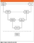
Figure 4
The requirements in the URS are broken down into further detail in a functional specification. The classical way of describing the difference between the two documents is that the URS defines what is required of the system and the functional specification describes how it is to be achieved. From the functional specification, the configuration of the software is documented in a configuration specification. This third document details the functions that will be configured and how this will be done, which sounds good but what do we really mean by a configuration specification in practice?
Table I shows the simplest type of configuration specification for spectrometry software. This is simply a list that indicates if specific functions were turned on or off. As the system is used in a regulated environment, the security manager functions were all turned on to provide the most appropriate security and to ensure data integrity. There are further elements in this software that must be configured but this is the configuration that occurs at the start of the installation process. A more complex configuration specification is illustrated in Table II, which is taken from a LIMS. Looking at the table, there is a column containing the requirement number of each configuration element that links back to the URS for traceability (shown in the left-hand column), the item to be configured, and finally, in the right-hand column, the configuration settings themselves.
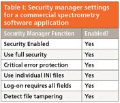
Table I: Security manager settings for a commercial spectrometry software application
You might ask why document the configuration of an application? You want to because it is good practice is my answer. You want to record how you have set up the software so you can understand how it handles your data and protects them. If you look in Table II, there are the column headings that are configured for a specific laboratory. For example, there are several requirements documenting how many decimal places will be used to report numbers. This is important as you will want to know from both scientific as well as disaster recovery perspectives.
Back to the life cycle model in Figure 4: The hardware (platform) running the operating system would be installed first and checked out and then the application will be installed and checked out. There will be a hardware IQ and application IQ and possibly an operational qualification (OQ) performed by IT and the vendor, respectively. Once the system has been installed, the software can be configured and then tested against the configuration specification. The configured system can then be tested against the functional specification, and then the overall system can be tested against the URS for user acceptance testing or performance qualification (PQ). In this model, it is difficult for a user or system owner to differentiate between configuration, system, and performance testing — well it's all testing, right? Partially, look at the configuration settings in Table I and Table II: How would you test these elements? Wouldn't it be easier to integrate some of this testing together?
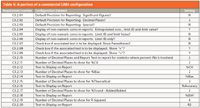
Table II: A portion of a commercial LIMS configuration
Category 4 Life Cycle Model: Simple Version
Oh dear, that philosophical question "Are you lazy?" has just come up again. Let's look at an alternative approach to a life cycle that we can apply more effectively in the laboratory and look at the simplified model shown in Figure 5. Again, we start with the URS to define what we want the system to do and then we define the configuration of the software in the configuration specification. Being realistic, you will write the configuration specification only after you have purchased the software and have been trained in its use, so there is a time delay implicit in this life cycle model.
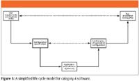
After installing and qualifying the software at the bottom of the life cycle model, the software is configured against the configuration specification, and this is verified but not tested. The whole testing and remaining verification can be condensed into a single phase of user acceptance testing or PQ.
You'll note that the main difference between the full category 4 life cycle model shown in Figure 4 and that shown here in Figure 5 is that there is no functional specification. You might ask why this is the case. The rationale is that much of the software we use in the laboratory does not require one. The GAMP 5 in Appendix M4 notes that the functional specification does not need to be owned by the user (2), which means that it can be written either by an IT or informatics group or the vendor of the software. If we take the view that the vendor has written this document, we can verify this during an vendor audit and then we do not need to write another one. However, GAMP 5 also notes that there should be adequate specification to ensure traceability and adequate test coverage (2). Indeed, there should be, as this is good software engineering and business practice. You will know through the traceability matrix that everything you specified in the URS was delivered in the final system (7,8).
Compare Table I with Table II, and you will see that the configuration requirements in Table II are numbered, which will enable traceability far more easily than requirements that are unnumbered. The "C" before the number indicates that it is a configuration requirement and this can be traced back easily to the requirement in the URS via the traceability matrix. An alternative approach that could be taken is to take a URS requirement and its number (for example, 3.2.2), and all configuration associated with this will be numbered 3.2.2.1, 3.2.2.2, etc. However, this can become a little laborious to maintain, especially if requirements change over the life of a project.
Overall, the aim of the simplified category 4 model is to reduce the complexity of work and associated documentation required to validate laboratory software compared with the standard GAMP 5 life cycle model for this category of software.
Category 5 Life Cycle Model
Now we get to the highest risk software, category 5, with a life cycle model shown in Figure 6. On the left-hand side, we have the four specification phases consisting of URS, functional specification, design, and module specifications. The new documents for this category of software are the design and module specifications. These are the further decomposition of the functional specification into the definition of the units and modules of code that will be written in the build phase of the life cycle. Although the model shows four levels of specification, I have so say I have never seen this in practice, even when auditing commercial software companies. The most I have seen is three levels and usually, the design and module specifications are condensed into a single software design specification.
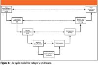
Figure 6
After programming and informal testing by a software developer in the code software units and modules phase in Figure 6, the related units of code are combined into modules that are tested formally to find and fix errors. When errors have been fixed and retested, the modules are combined to form the system, and each system build is tested formally to identify errors and confirm that it works as expected against the functional specification. When the software developers have finished their work, the system is passed over to the users, who will evaluate it to check that the system works according to their requirements in the URS and then feedback their thoughts and comments. Typically, there will be several release candidates that will be shown in some form to the users, then after user enhancement requests and software bug fixes, the final system build is released for formal user acceptance testing (PQ) and then operational use.
Category 4 with Category 5 Extensions Life Cycle Model
Just when you thought things could not get any worse, along comes a really complex life cycle model! As mentioned at the start of this column, software is a continuum and we must not compartmentalize software into a single silo, so the life cycle shown in Figure 7 is a combination of category 4 and category 5 software. This is based upon the purchase of a category 4 product that is then configured, and as the product has a scripting language, there are custom enhancements or macros written to undertake tasks that the configured product cannot perform. Examples of this are LIMS and macros for spectrometry software such as an NIR or NMR instrument. Alternatively, using a recognized programming language (for example, C++ or Visual Basic), the custom software is bolted onto the configured product.
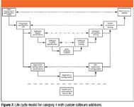
Figure 7
In Figure 7, we can see the two life cycles integrated together, the category 4 elements are linked together by the thick bold lines, and category 5 elements have the lighter lines connecting them. Congruence (that is, testing or verification) between the left- and right-hand sides of the model is depicted by two different types of horizontal dashed lines to denote category 4 and 5 software, respectively. As usual, the jumping-off point for this and any life cycle model is a URS that covers the whole system and this triggers the writing of the functional specification again for the whole system. After this, the two life cycles divert. The category 4 life cycle goes through the phases that have been described earlier in this column.
The category 5 life cycle is nested within the category 4 life cycle but is only applied to the custom elements that are written specifically to ensure that the overall system meets business needs. From the functional specification are written software-design and software-module specifications. The former document covers all the custom software and latter document covers individual modules. However whole the theory is in practice, there might only be a single software design document that is written before the coding begins. Again, as described in the category 5 life cycle, there will be module testing, after which the released module will be integration tested to see that it works with the configured application. Once completed, the whole system will undergo system- and user-acceptance testing before release.
You'll appreciate that this is a more complex process than for category 4 software and therefore, it is easier to change the way the laboratory works to match the standard or configured software rather then write custom software.
Technical Specification
One element and document that is missing from all the life cycle models is the technical specification, mainly for networked category 4 and 5 systems. This will define the computing platform and system architecture and is the basis for the purchase, installation, and qualification of the hardware and operating system before the installation and qualification of the application. This document will specify the production environment and any additional environments such as test, training, and validation as well as the architecture (will the application and database be on the same or different servers?).
Summary
Life cycle models for GAMP 5 categories of software have been discussed and in some cases simplified to reduce the amount of work required for validation in a laboratory context. Looking at the different life cycle models, nonconfigurable product software (category 3) is the simplest to validate. Compare this with the models for configurable product (category four) with custom modules (category 5) or custom applications (category 5), and this is the most complex and highest risk software. Knowing and understanding the differences will make your job easier when you come to select and validate the software you select or specify.
R.D. McDowall is principal of McDowall Consulting and director of R.D. McDowall Limited, and "Questions of Quality" column editor for LCGC Europe, Spectroscopy's sister magazine. Address correspondence to him at 73 Murray Avenue, Bromley, Kent, BR1 3DJ, UK.
References
(1) R.D. McDowall, Spectroscopy 24 (6), 22 (2009).
(2) Good Automated Manufacturing Practice (GAMP) guidelines version 5, International Society for Pharmaceutical Engineering, Tampa, Florida, 2008.
(3) Good Automated Manufacturing Practice (GAMP) guidelines version 4, International Society for Pharmaceutical Engineering, Tampa, Florida, 2001.
(4) Computerised Systems in GXP Environments (PI-011), Pharmaceutical Inspection Convention / Pharmaceutical Inspection Cooperation Scheme (PIC/S), Geneva, Switzerland, 2004.
(5) R.D. McDowall, Quality Assurance Journal 12, 64–78 (2009).
(6) 21 CFR 211, Current Good Manufacturing Practice regulations.
(7) R.D. McDowall, Spectroscopy 23 (11), 22–27 (2008).
(8) R.D. McDowall, Spectroscopy 23 (12), 78–84 (2008).
