Comparison of Different Sample Preparation Procedures for the Determination of RoHS/WEEE Regulated Elements in Printed Circuit Boards and Electrical Components by EDXRF
This study evaluates the merits of different sampling techniques for the determination of a group of hazardous elements in printed circuit boards as defined by the European Union, RoHS, and WEEE.
Manufacturers and suppliers of electronic and electrical products to countries within the European Union (EU) must comply with RoHS (1) and WEEE regulations (2).
Typical products that currently fall under these regulations include
- Large and small household appliances
- Computer technology
- Telecommunications equipment
- Consumer products
- Lighting equipment, including light bulbs
- Electronic and electrical tools
- Toys and leisure and sports equipment
Under these directives, the use and disposal of six hazardous metals–materials used in the manufacture of these products is restricted. The six hazardous materials defined in the RoHS/WEEE regulations are lead (Pb), mercury (Hg), cadmium (Cd), hexavalent chromium (CrVI ), polybrominated biphenyls (PBB), and polybrominated diphenyl ethers (PBDE). The maximum permitted concentrations for these materials are 1000 ppm (except for cadmium, which is limited to 100 ppm) by weight of homogeneous material. The term "homogeneous" means that the limits do not apply to the total weight of the final product, or even to an individual item in the product, but to any single component that could be mechanically separated out. So, for example, in a printed circuit board, this would refer to the plastic substrate material, the metallic connecting wire, the plastic sheath covering a cable, or any other material that is used in the manufacturing process of the board.
XRF spectroscopy is the most widely used analytical technique for carrying out the rapid trace element testing of electrical equipment to meet the RoHS/WEEE requirements. Small, portable, or handheld instruments using the principle of EDXRF instruments are used routinely for checking various locations on a component or piece of equipment to determine whether that item is in compliance. However, the inherent problem with this technique is that X-ray beam diameter is typically only a few hundred micrometers to a few millimeters. So if the component is extremely small, accurate quantitation could be problematic. In addition, if there is any elemental segregation in the circuit board material or electrical component, the composition could be different depending upon where the X-ray beam strikes the sample. These potential limitations could mean that an item can pass or fail the RoHS/WEEE levels based upon a measurement that is not truly representative of the entire component.
It is therefore extremely important to understand these sampling–heterogeneity issues by measuring the elemental composition of the component as it is received and comparing it with the same sample ground up into a homogeneous mixture. This information is critical in order to make a valid assessment as to whether use of the rapid "spot checking" XRF method of electronic components is accurate and truly representative of the trace element composition of that sample. Before we discuss the experimental details of the methodology, let us remind ourselves the principles of XRF, so we can get a better understanding of its strengths and weaknesses for this type of analysis.
Principles of XRF
The principles of XRF spectrometry are well-documented in the literature (3). A sample is irradiated with a beam of high-energy X-rays to excite the ground state atoms of the elements being measured. As the excited electrons fall back into a lower energy orbital, fluorescence occurs and secondary X-rays are emitted that are characteristic of those elements present in the sample. The individual X-rays then are separated and measured via a system of crystals, optics, and detectors. Elemental concentrations in unknown samples are quantified by comparing the X-ray intensities against known calibration standards of a similar matrix to the sample.
XRF is not considered a truly ultratrace technique like atomic spectroscopic techniques, but typically is used to quantitate elemental concentrations from parts-per-million levels up to percentage levels of elements in the periodic table from Na (atomic mass 23) up to U (atomic mass 238). It generally is not used for elements below Na, because fluorescence is significantly less in this region, due to the shallow depth and angle of penetration of the emitted X-rays. Apart from the elemental coverage, the analytical domain of XRF is very similar to that of arc or spark emission optical techniques. However, the major benefit of XRF over arc/spark emission is that it can analyze both conducting and nonconducting materials as well as inorganic and organic matrices with minimal sample preparation (4).
It is important to emphasize that XRF is available in two separate configurations: energy-dispersive (ED) and wavelength-dispersive (WD) XRF. The EDXRF approach measures the intensity of the photon energy of the individual X-rays generated, whereas in WDXRF spectrometry, the polychromatic beam emerging from a sample surface is dispersed into its monochromatic wavelengths with an analyzing crystal. A specific wavelength, corresponding to the analyte of interest, is then calculated from knowledge of the crystal and the diffraction angle. It generally is recognized that WDXRF offers higher performance than EDXRF, because of its more sophisticated optical configuration. This translates into lower detection capability (particularly for the lighter elements), higher precision, wider dynamic range, and superior spectral resolution. This makes WDXRF the preferred technique for research-type work and applications that require the highest performance. However, the major benefit of EDXRF is that it is less expensive, and is physically more compact. This makes it the technique of choice for field applications in which portability is important and for handheld XRF devices that carry out the high-throughput screening of an industrial production line like metallurgical samples or for checking toxic elements in children's toys or electrical equipment (5).
It is also important to emphasize that accurate quantitation in XRF is based upon the availability of good calibration standards of a similar matrix to the unknown samples. When X-rays are directed onto a solid or liquid sample, they are absorbed by the matrix elements before they eventually reach and excite the analyte atoms. If the concentration of the matrix changes for any reason, the absorption of the X-rays also will change. This will result in different excitation characteristics, which will ultimately impact the intensity of the emitted secondary X-rays. There are ways to minimize these matrix effects, but with EDXRF in particular, it is very important to match the calibration standards with the unknown samples in order to obtain good accuracy. However, for applications in which high accuracy is not required, such as in the checking of electrical equipment, where known calibration standards are not available readily, XRF is ideally suited for the high-throughput pass–fail screening of unknown samples using semiquantitative routines.
Experimental Details
The experiment was split into two sections. The first set of samples was taken from a printed circuit board that was known to have failed the RoHS/WEEE regulations, while the second part of the experiment involved taking some of the circuit board electrical connectors and components. For each experiment, two sets of samples were analyzed. The first set of samples were the individual parts of the circuit boards and electrical components with minimal sample preparation, while the second set of samples were the same parts ground up into a fine powder with a cryogenic (using liquid nitrogen) laboratory grinding mill (6770 Freezer/Mill, SPEX SamplePrep, Metuchen, New Jersey) (6). For both experiments, each set of samples were analyzed for bromine, cadmium, chromium, lead, and mercury using the semiquantitative capability of an EDXRF system (S2 Ranger, Bruker AXS, Madison, Wisconsin) (7). Calibration curves were created using polyethylene standards spiked with known concentrations of RoHS/WEEE elements. It should be noted that the instrument used in this study is a small benchtop EDXRF system that is based upon similar technology to the commercially available handheld devices, the major difference being that calibration standards were used for this study, whereas handheld devices are typically standardless. Before we describe the sampling procedures used in this study, let us briefly discuss the principles of cryogenic grinding.
Principles of Cryogenic Grinding
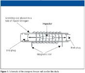
Cryogenic grinders are basically laboratory mills that chill samples in liquid nitrogen and pulverize them into a fine powder with some kind of impacting device. The freezer mill technology used in this study incorporates an insulated tub into which liquid nitrogen is poured. The grinding mechanism is a magnetic coil assembly suspended in the nitrogen bath.
Each sample is placed in a closed grinding vial along with a metal impactor and the vial is then inserted into the coil assembly and lowered into the liquid nitrogen. When the sample is chilled thoroughly, which is typically 10–15 min, grinding begins. The magnetic coil shuttles the impactor rapidly back and forth, pulverizing the sample against the end plugs of the vial, as shown in Figure 1. When the grinding cycle is complete, the vial is removed from the freezer mill, emptied, and cleaned.

Figure 1
It's well accepted that chilling materials with liquid nitrogen to temperatures approaching -200 °C, has two important benefits for sample preparation. First, it makes flexible samples extremely brittle so they can be pulverized by impact milling relatively quickly, and second, it preserves structural and compositional aspects usually damaged or lost during room temperature pulverizing. Virtually any kind of solid sample can be pulverized with this kind of technology, including bones, rocks, ceramics, polymers, plastics, metals, asbestos, teeth, and plant materials. It is simply a matter of choosing the optimum vial and impactor, based upon the type of sample and the suite of analytes being determined. A typical turnaround time is in the order of 45–60 min/sample.
Sampling Procedure for the Analysis of Noncompliant Circuit Boards, Electrical Connectors, and Components by EDXRF
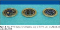
Three circular, 40-mm diameter samples were cut from different locations on a circuit board known to be noncompliant with RoHS/WEEE regulations, as shown in Figure 2. Both the front and back sides of the circuit board were analyzed by EDXRF.

Figure 2
Next, the same circuit board samples were cut into small pieces and all copper items were removed. Each sample was placed into a chromium-free vial and submerged in liquid nitrogen in the freezer mill for 20 min. Samples were then ground for three 2-min cycles at 10 Hz, using a 15-min precooling segment prior to grinding and 2-min cooling segments between cycles. Following this treatment, unground material was then removed from the powdered sample and submerged again in liquid nitrogen for 20 min. This material was then returned to the freezer for additional grinding.
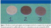
Ground samples were pressed into pellets measuring 40 mm in diameter by layering the sample material onto a base of boric acid and pressing at 30 tons with a laboratory press (3630 X-Press - SPEX SamplePrep). The final pelletized samples are shown in Figure 3. These pellets were then analyzed by EDXRF, as described earlier.

Figure 3
For the second part of the investigation, the connectors and components were removed from the circuit boards, sorted by type, placed into 40-mm sample cups covered with Mylar film, and analyzed by EDXRF. The samples were then ground in the freezer mill using the same protocol described previously, and analyzed not as a pressed pellet, but as loose powders. The individual connectors and components sorted by type are shown on the left, while one of the ground samples (sample C in Table II) is shown on the right in Figure 4.

Figure 4
Results and Discussion
Analysis of the Printed Circuit Board
Quantitative results for the three sections of the circuit board (front and back) using both sampling procedures are shown in Table I. The elements cadmium and mercury were not detected in any of the samples before or after grinding and, therefore, are not shown in the table. Bromine levels exceeded RoHS/WEEE limits for all samples. However, by switching to nonbrominated flame retardants in the manufacture of circuit boards, this obstacle could be overcome.

Table I: Quantitative results (ppm) for Cd, Cr, and Pb by EDXRF in three sections of the printed circuit board using the two sampling procedures described
The results for chromium and lead are more interesting. While chromium was not detected in any of the samples prior to grinding, it was found in samples 1 and 2 after they were ground and pressed into pellets. In particular, sample 2 was found to contain 1166 ppm of chromium, which exceeds the RoHS/WEEE maximum limit of 1000 ppm. This was not contamination from the sampling container, because the vial was made from a chromium-free hardened steel. Lead levels were measured within the acceptable range in the cut disc samples, but the results increased significantly in samples 1 and 2 after grinding and as a result, both samples then failed to meet RoHS/WEEE regulation levels. These higher levels of chromium and lead in the pelletized powders appear to be real and indicate that the EDXRF is generating spurious results because of the elemental heterogeneity of the circuit board.
Analysis of the Electrical Connectors and Components
Quantitative results for the various electric connectors and components (samples A-E) before and after grinding are shown in Table II. As in the first experiment, mercury was not detected in any of the samples. Since sample E was a steel alloy, containing over 95% iron and small amounts alloying elements, the presence of chromium was expected. Interestingly, cadmium was detected in sample E before grinding, but not after. This could indicate that the XRF analysis of the loose metal connectors occurred at a point where the instrument was able to detect a cadmium signal. However, after grinding, the cadmium level in the mixed, homogenized powder was, in all probability, too low to be detected.

Table 2 Table II: XRF results (ppm in the solid) for the various electric connectors and components before and after grinding
Bromine concentrations increased dramatically for samples B–E after grinding, and as a result were all above the RoHS/WEEE limits. Lead levels increased in all cases, but significantly for samples B–E. Sample D just met RoHS/ WEEE limits for lead before grinding, but failed by a wide margin after grinding. Again, this could indicate that EDXRF might not be the optimum technique for the measurement of these elements in loose circuit board components and connectors where the elements are distributed throughout the sample in a segregated manner.
Conclusion
This is just a preliminary study, but it clearly indicates that the method of sample preparation and the measurement location of the circuit board have a significant impact on the XRF results. Concentrations of metals were generally much higher for the ground-up, homogeneous samples compared to the individual parts of the circuit boards and connectors, because of heterogeneity sampling issues. This means that spot-checking various locations on a circuit board with a portable or handheld EDXRF device could produce misleading results, based upon the elemental segregation of the sample. On the other hand, processing a section of the board or component to ensure a homogeneous sample is likely to yield a result that is more representative of the overall composition of the circuit board. More work needs to be done to confirm these findings, but based upon the data generated in this investigation, extreme care should be taken when testing all kinds of electrical equipment for RoHS/WEEE regulated elements using rapid XRF screening methods. And to be absolutely certain that the reported results are truly indicative of the components being tested, serious consideration should be given to the alternative sampling procedures described in this study.
John E. Martin, Lea L. Anderson Smith, and Gloria Adjei-Bekoe are with Spex Sample Prep, Metuchen, New Jersey, and Robert Thomas is with Scientific Solutions, Gaithersburg, Maryland. Direct correspondence to: landerson-smith@spexcsp.com.
References
(1) Directive 2002/95/EC of the European Parliament and the Council of the European Union on Restriction Of the use of Hazardous Substances (RoHS) in electrical and electronic equipment: - http://www.rohs.gov.uk/Docs/Links/RoHS%20directive.pdf , (2002)
(2) Directive 2002/95/EC of the European Parliament and the Council of the European Union on Waste Electrical and Electronic Equipment (WEEE): - http://www.berr.gov.uk/files/file29931.pdf (2002).
(3) E.P. Bertin, Introduction to X-Ray Spectrometric Analysis (Plenum Press New York, 1978).
(4) H.W. Major and B.J. Price, Plastics Eng. 46 (8), 37–39 (1999).
(5) V. Thomsen and D. E. Schatzlein, Spectroscopy 17 (7), 14–21 (2002)
(6) Product Specifications for 6770 Freezer Mill, Spex Sample Prep, Metuchen, NJ: http://www.spexcsp.com/sampleprep/catalog/aid34.html
(7) Product Specifications for S2 Ranger EDXRF, Bruker AXS, Madison, WI: http://www.bruker-axs.com/s2_ranger.html

LIBS Illuminates the Hidden Health Risks of Indoor Welding and Soldering
April 23rd 2025A new dual-spectroscopy approach reveals real-time pollution threats in indoor workspaces. Chinese researchers have pioneered the use of laser-induced breakdown spectroscopy (LIBS) and aerosol mass spectrometry to uncover and monitor harmful heavy metal and dust emissions from soldering and welding in real-time. These complementary tools offer a fast, accurate means to evaluate air quality threats in industrial and indoor environments—where people spend most of their time.
NIR Spectroscopy Explored as Sustainable Approach to Detecting Bovine Mastitis
April 23rd 2025A new study published in Applied Food Research demonstrates that near-infrared spectroscopy (NIRS) can effectively detect subclinical bovine mastitis in milk, offering a fast, non-invasive method to guide targeted antibiotic treatment and support sustainable dairy practices.
Smarter Sensors, Cleaner Earth Using AI and IoT for Pollution Monitoring
April 22nd 2025A global research team has detailed how smart sensors, artificial intelligence (AI), machine learning, and Internet of Things (IoT) technologies are transforming the detection and management of environmental pollutants. Their comprehensive review highlights how spectroscopy and sensor networks are now key tools in real-time pollution tracking.