Decimal Versus Binary Representation of Numbers in Computers
The dichotomy created by the advent of computers and brought up by the title of this column was a major quandary in the early days of the computer revolution, causing major controversy in both the academic and commercial communities involved in the development of modern computer architectures. Even though the controversy was eventually decided (in favor of binary representation; all commercially available computers use a binary internal architecture), echoes of that controversy still affect computer usage today by creating errors when data is transferred between computers, especially in the chemometric world. A close examination of the consequences reveals a previously unexpected error source.
So what’s the cause for all the furor? Basically, it’s because the “natural” smallest piece of internal hardware of a computer (a “bit”—contraction of a binary digit) has two states: “on” and “off.” The literature assigns various name pairs to those states: on/off; high/ low; true/false, or one of the various others depending on the application. The name pair of special interest to us here is “1/0.” Conceptually, the 1/0 dichotomy can be used to implement several different underlying concepts, including Boolean logic states and numbers. Regardless of this interpretation, the state of the circuit is represented by an actual voltage at the output of the circuit. Typically, the state “0” would correspond to an actual zero voltage at the output, whereas a “1” state would represent some non-zero voltage; five volts is the common value. Actual hardware can transiently have intermediate values while changing from one state to another. As an example, when analyzing the function the hardware performs, intermediate voltages are considered disallowed; in actual hardware, intermediate voltages only occur briefly during a change of state.
Hardware can be devised to create basic Boolean logic functions such as “AND,” “OR,” and “NOT.” Combinations of those basic functions can be, and are, used to create more complicated logic functions, and they can also perform functions George Boole never conceived of as long as the output signal of the hardware is a voltage that corresponds to either a “zero” or a “one.”
So much for interpreting 1/0 as logic. What we want to know is how that same concept is used to represent numbers. It is very straightforward; it’s done the same way that we do with decimal numbers. We call our usual number system “decimal,” which is also called base-10 because it consists of 10 digits: “0,” “1,” “2,” “3,” “4,” “5,” “6,” “7,” “8,” and “9” (10 different symbols representing the 10 digits). In contrast, binary (base-2) numbers are only allowed two states, with symbols representing the two states, the zero and one described above. As a short aside, mathematicians have described number systems with different numbers of states (and corresponding symbols). For example, in a ternary number system, a digit can have three states (“0”, “1”, and “2”), although the issue with this system is that it is not so easily implemented in hardware. That’s one reason you never see it in day-to-day use. Donald Knuth discusses some of the more exotic number systems mathematicians have devised in his masterwork (see section 1.2.2 of [1]), such as number systems with fractional and even irrational bases (“There is a real number, denoted by e = 2.718281828459045..., for which the logarithms have simpler properties” (see page 23 in [1]). That means that e, a number that is not only irrational, but transcendental, can be the base of a number system. But we won’t go there today.).
In fact, some of the alternative number systems are sometimes seen in computer applications. In particular, the octal (base-8) and the hexadecimal (base-16) number systems are sometimes used in special computer applications and for pedagogical purposes in instructional texts. Octal- and hexadecimal systems are particularly well-suited to being used for representing numbers in computers by virtue of the fact that they are both powers of two. Thus, they can easily be converted to or from their binary representation. Octal numbers can be expressed simply by taking the bits of a binary number in groups of three, and hexadecimal numbers can be expressed by taking the bits of a binary number in groups of four. Conversion to other bases is more complicated and we leave that for another time.
Sometimes, we need to accommodate another limitation of the number systems we use. For example, all number systems have one and the same limitation—the number of symbols that are used to represent numbers is finite and limited. So how do we represent numbers higher than those that can be represented with a single symbol?
For example, the binary system only allows for two states, so how can we count to values higher than 1? Again, the answer is in a similar fashion to how we do it in the decimal number system. And how is that? The answer is that we use positional information to enable counting beyond the limit of the number of symbols available. When we’ve “used up” all the symbols available to us in one place of the number, we add another place, and in it we put the number of times we’ve “run through” all the available symbols in the next lower place.
Regardless of the number system, another limitation is that there are only a finite number of symbols to represent the digits, so how can we keep counting to higher numbers when we’ve “used up” the available symbols? Of all the number systems we’ve mentioned, one of them encounters this problem—the hexadecimal system, which requires 16 different symbols, six more than our usual numbers do. The solution generally applied is to co-opt some of the alphabetic characters as numerical digits; typically the letters a–f are used to represent digits with values of 10 to 15.
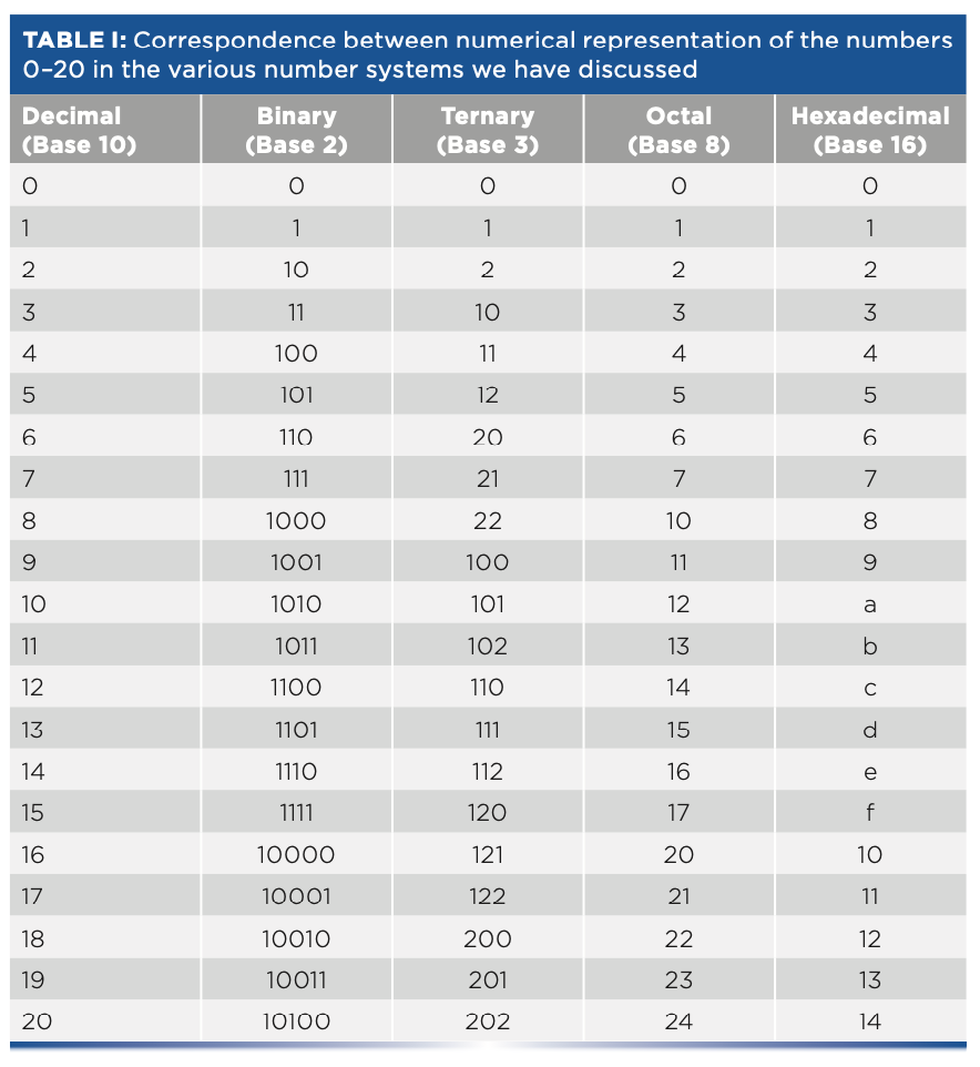
To see how this all works, Table I shows how the first 20 numbers (plus zero) are represented in each of these various number systems. Online utilities are available to convert from one number base to another (an example is in the literature [2]). It is obvious that there is danger of confusion because the same symbol combination could represent different numbers depending on which number system it is being used in. In cases where such confusion could arise, the number system is indicated with a subscript after the number. Thus, for example, 1002 = 410 (read as: “one-oh-oh in base two equals four in base ten”), whereas 1003 = 910 (read as “one-oh-oh in base three equals nine in base 10,” as we can see from Table I), and the subscripts tell us which is which. How do we then interpret the subscripts? Those are decimal!
Numbers in Computers
Once they are constructed, computers have no problem dealing with any of those systems of numbers, although some are more complicated for engineers to set up than others. However, people have problems with them. For example, consider one very simple question: “is ef7da116 greater or less than 11001011101010000102?” I’m sure that any of our readers could, with enough time and effort, work out the answer to that question, but the point is that it doesn’t come easily; certainly, it’s not as easy as answering the similar question “Is 510 greater or less than 1310?”
We’re used to working with decimal numbers. At the beginning of the computer revolution and even in the times before then when “computers” meant multi-million-dollar devices attended by “high priests” (as they were perceived at the time), the question of how to represent numbers inside a computer arose, and it was an important question. Back then, computers were used to perform calculations involving multi-million-dollar business transactions (at a time when a million dollars was worth something!), and the results needed to be checked to ensure that the computers were working properly and providing correct answers. Only people could do that, and they had to do it using decimal representation. That created a strong incentive to have the computers also use decimal representation so that the computers’ internal numbers could easily and directly be compared with the manual computations.
Eventually, the need for people to comprehend what the computers were doing was addressed with a hybrid approach called binary-coded decimal (BCD). Numerical information was maintained internally as decimal values, where each digit 0–9 was expressed individually in binary. This process required only four bits per digit, just like hexadecimal, but only 10 of the 16 possible combinations were allowed to be expressed. This process allowed combinations to be put into a one-to-one correspondence with the ten decimal digits. This scheme made it easier for humans to interpret, but it carried some disadvantages: 1) it increased the complexity of each digit’s circuitry to prevent it from entering a disallowed state, which made computers more expensive to construct and more subject to breakdowns; 2) arithmetic circuits were also more complicated to enable decimal instead of binary operations; and 3) the circuitry for all four bits for each digit had to be present for every decimal digit throughout the computer, even though only 10 of the possible 16 combinations of those four bits were used.
As a result, it was a very inefficient use of the hardware. To represent numbers of up to (say) 100,00010, all components, wiring, controls, memory, and interconnects required 6 x 4 = 24 bits of (more complicated) hardware for BCD numbers compared to only 17 bits for binary numbers. The discrepancy increased as the magnitude of the numbers that needed to be accommodated increased. In the days before large-scale integration techniques were available, that allowed an entire computer to be fabricated on a single silicon chip, which imposed a substantial cost penalty on computer manufacturing because the extra bits had to be included in the control, processing, memory, and every other part of the computer. Some “tricks” were available to reduce this BCD penalty, but the “tricks” often had the side-effect of exchanging higher hardware cost for slower computation speed, and it was still more expensive to build a computer for BCD numbers than for binary numbers.
In fact, remnants of BCD number representations still persist in the form of any device that has a built-in numeric display. Typically, those consist of a seven-segment LED (or other electro-optical technology) are arranged so that activating appropriate segments allow any numeral from zero to nine to be displayed. Although often combined into a single circuit, that requires conceptually two stages of decoding to implement. For each digit displayed, four binary bits are decoded to one of the 10 decimal digits, then each of those is decoded to determine which of the LED segments needed to be activated.
Where Are We Today?
In modern times, computers are based on micro-controllers that often include, as mentioned above, an entire computer on the silicon integrated circuit (the “chip”). Because the “fab” needed to construct such a computer costs several millions of dollars, efficiency in using silicon “real estate” is of paramount importance, so modern computers use binary numbers for their internal operations, whereas input (accepting data), and output (providing results), both of which involve human interaction, are done using decimal. With the increases in computer speed and reliability achieved over the years, the conversions between the two domains is performed via the software, bypassing the older problems previously encountered.
The Problem
However, we’re not out of the woods yet! We have not yet accounted for all the numbers and types of numbers we expect our computers to deal with. In particular, ordinary scientific measurements need to deal with very small (for example, the size of a proton is 8 x 10-16 meters) and very large quantities (the universe is (as of this writing) known to be roughly 92 billion (9.2 x 10¹⁰) light years in diameter and 14 billion (1.4 x 10¹⁰) years old; a mole consists of 6 x 10²³ atoms, and so forth). Ordinary numbers were insufficient to deal with the need to represent these very small and very large quantities. As a result, scientific notation was devised to help us express these extreme quantities, as I just did at the beginning of this paragraph.
There is a similar problem in computer expression of numbers—how to deal with very large and very small numbers. A separate but related problem is how to represent fractions; note that the examples and number systems described above all deal with integers. However, computers used in the “real world” have to deal with fractional values as well as very large and small ones. The computer community has dealt with that problem by devising a solution analogous to scientific notation. Computers generally recognize two types of numbers, maintained by the software and independent of the number base used by the hardware. These are designated “integers” and “floating point” numbers. All the number systems we’ve discussed above, regardless of the number base, are integers. Although a mathematician might disagree with this definition, for our purposes here we consider “integers” to mean the counting numbers (as in Table I). Integers are generally limited to values from zero to a maximum determined by the number of bits in a computer “word” (which is hardware-dependent) and their negatives, regardless of the number base. Table I tells us (almost) everything else we need to know right now about integers.
The other type of numbers, which are recognized and used internally by computers, is analogous to scientific notation and called “floating point” numbers. Floating point numbers come in a variety of implementations, which are designated Float-16, Float-32, Float-64, and so forth, depending on how many bits of memory are allocated by the computer software to each “floating point” number. Generally, that is a small multiple of the size of a computer “word,” which is the number of bits, determined by the hardware, that the computer can handle simultaneously (and not incidentally, usually also determines the maximum size of an integer). Generally, each number is divided into four parts: an exponent; a mantissa; sign of the exponent; and sign of the mantissa.
Because different manufacturers could split up the parts of a floating point number in a variety of ways, this scheme could—and did—lead to chaos and incompatibility problems in the industry, until the Institute of Electrical and Electronic Engineers (IEEE), a standards-setting organization for engineering disciplines, stepped in (3). Comparable to the American Society for Testing and Materials (ASTM) (4,5), IEEE created a standard (see IEEE-754) (6) for the formats of numbers used inside computers. The standard defines two types of floating point numbers, single precision and double precision. Each is defined by splitting a number into two main parts, an exponent and a mantissa. Per the standard, the 32 bits of a single-precision number allocate 23 bits for the mantissa of the number, which gives a precision equivalent to 6–9 decimal digits depending on the magnitude of the number. Double precision uses 64 bits to represent a number and actually provides more than double that of single precision, the 52-bit mantissa of an IEEE double-precision number is equivalent to a precision of approximately 16 decimal digits.
However, we’re still not out of the woods. There’s no flexibility in the binary representation of data in the computer, especially if they are, in fact, IEEE single-precision numbers, but a problem arises when someone is careless when changing the representation to decimal for external use, such as transferring the data to another computer, displaying it for people to read, or performing computations on it after conversion to decimal. It doesn’t matter what the data is; it’s a fundamental problem of number representations. Converting the internal values in your computer to a format with an insufficient number of decimal digits is the underlying source of a problem, and that will affect the results of any further calculation performed on that data.
The IEEE specifications include the following proviso: if a decimal string with at most six significant digits is converted to IEEE 754 single-precision representation and then converted back to a decimal string with the same number of digits, the final result should match the original string. Similarly, if an IEEE 754 single-precision number is converted to a decimal string with at least nine significant digits, and then converted back to single-precision representation, the final result must match the original number (3). So when you write out your data to a file and the data is written as decimal numbers, the data stored in the file will have an insufficient number of decimal digits of precision, and contain neither the six-and-a-half digits worth that the internal binary representation of the data contains nor the nine that is recommended. When that data is read into another computer, the binary number generated in the second computer is not the same as the original binary number that gave rise to it. Performing computations, such as a derivative or other processing, does not fix the problem, because the new data will also be subject to the same limitations. Thus, transferring data to a different computer so that a different program can work on it may not give the same results as performing the same computations on the original data.
This discussion is pertinent to some data-transfer standards. For example, JCAMP-DX (7) is a popular format for computer exchange of spectral data. The JCAMP-DX standard does not address the question of the precision of the data being handled; it permits data to be stored using an arbitrary number of digits to represent the original data. Therefore, an unwary user of JCAMP-DX may use an insufficient number of decimal digits to store spectral data in a JCAMP-DX file and later be surprised by the results obtained after the data has been transferred. For example, if the data is to be used for chemometric calibration purposes (for example, multiple linear regression [MLR] or principal component regression [PCR]), different results will be obtained from data after it has been transferred to a second computer than if it was obtained from the original data in the original computer.
How can this be fixed? As per the discussion above, any external decimal representation of the data must be formatted as a decimal string of at least nine decimal digits. Currently, examples of JCAMP-DX files I’ve seen sometimes use as few as five decimal digits. I have seen JCAMP-DX files written by current software packages that wrote the spectral data using as few as six or seven decimal digits, which is better but still short of the nine required. I am not completely convinced that nine digits is sufficient, although at least it errs on the side of safety. The reasons for my doubt are explained in the appendix below. Therefore, rewriting the code you use to export the data, so that it writes the data out with nine significant digits, is a minimal requirement on what needs to be done. Any other programs that read in that data file must also accept and properly convert those digits.
Appendix
The below is a demonstration of the need for sufficient digits in the decimal representation of numbers converted from internal binary to decimal.
As in any number system, numbers are represented by the sum of various powers of the base of the number system. In a binary system as used in computers, the base is 2. Integers (counting numbers ≥1) are represented as the sum of powers of 2 with positive exponents: N = A020 + A121 + A222 + A323 + ...In the binary system, the multiplier, Ai, can only have values of 0 or 1; the corresponding power of two is then either in or not in the representation of the number.
Floating point numbers (for example, IEEE-754 single precision) are represented by binary fractions; that is, numbers less than 1 that consist of the sum of powers of 2 with negative exponents (for example, A12-1 + A22-2 + A32-3 + ...), where again, the various Ai can only have values of 0 or 1. When we convert this representation to decimal, each binary digit contributes to the final result an amount equal to its individual value. Table II presents a list of the exact decimal values corresponding to each binary bit. In Table II, these decimal values are an exact representation of the corresponding binary bit. If a conversion of a number from binary to decimal does not include sufficient digits in the representation, then it does not accurately represent the binary number. When the number is converted back to binary in the receiving computer, that number will not be the same as the corresponding number in the original. We discuss this point further below.
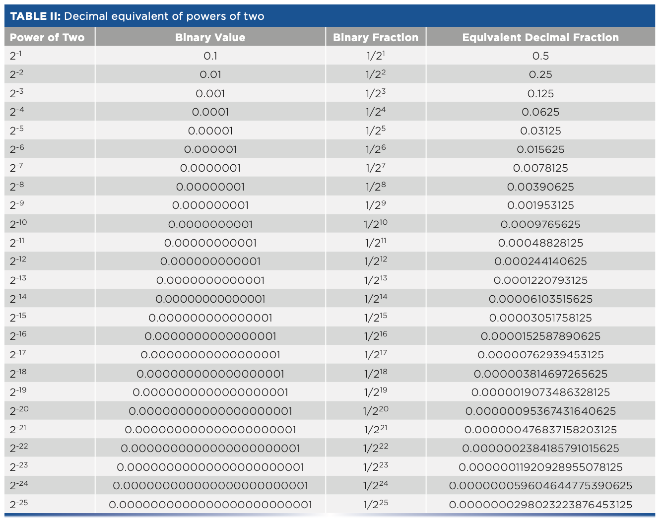
Numbers greater than 1 are represented by multiplying the mantissa (from Table II) by an appropriate power of two, which is available as the “exponent” of the IEEE-754 representation of the number. You should be careful when decoding the exponent because there are a couple of “gotchas” that you might run into; those are explained in the official standard (available as a PDF file online), in discussions of the standard, and in the literature (8) that provide details for creating and decoding the exponent, as well as the binary number comprising the mantissa.
There are several takeaways from Table II: first, we see that the number of decimal digits needed to exactly express the value of the number (including the leading zeroes) equals the power to which 2 is raised. We also see a repeating pattern: beyond 2-3, the last three digits of the decimal number repeat the sequence ...125, ...625, ...125.... From Table II, we also see that the statement “single precision corresponds to (roughly) 6.5 digits” (as derived from the IEEE-754 standard [3]) means that by virtue of the leading string of zeros in the decimal-conversion value, any bits beyond the 23rd bit will not affect the value of the decimal number to which binary representation is converted. Table II demonstrates that property because all of the first seven digits of the decimal equivalent are zero at and beyond the 24th bit. Therefore, when added into the 6-decimal-digit equivalent of the binary representation, the sum would not be affected.
At any stage, the exact decimal representation of a binary number requires exactly the same number of decimal digits to represent the corresponding binary fraction as the exponent of that binary digit. One point of this exercise was to demonstrate that because these representations of the binary digits are what must be added to give an exact representation of the original binary number, it therefore requires as many decimal digits to represent the binary number as there are bits in that binary number.
Errors in Representation
Above, we alluded to the fact that floating-point numbers are inexact, and that the degree to which they are inexact depends on the number base. For example, the decimal number 0.310 cannot easily be represented in the binary system. 2-110 = 0.510 is already too large and 2-210 = 0.25 is too small. We can add smaller increments to approach 0.3 more closely. For example, 0.0112 = 2-210 + 2-310 = 0.2510 + 0.12510 = 0.37510, which is again too large. And 0.01012 = 0.312510 is still too large, while 0.010012 = 0.2812510 is again too small. We’re closing in on 0.310, but clearly it’s not simple. Using an online decimal-to-binary converter (2) reveals that 0.01001100110011...2 is the unending binary approximation to 0.310 but any finite-length binary approximation is inevitably still in error. Different number bases are not always easily compatible.
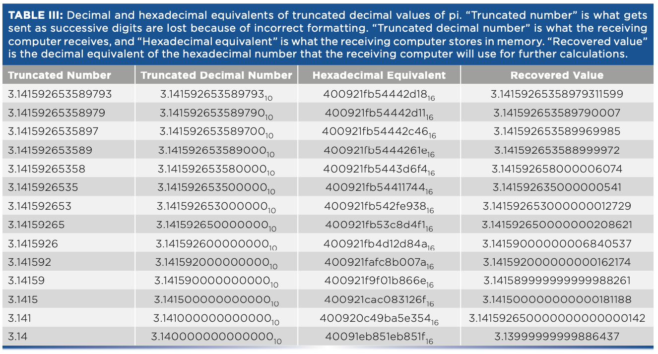
This issue becomes particularly acute when converting numbers from the binary base inside a computer to a decimal base for transferring data to another computer, and then back again. Ideally, the binary value received and stored by the recipient computer should be identical to the binary value sent by the initial computer. For some data transfer protocols, for example, JCAMP-DX allows for varying precision of the decimal numbers used by the transfer. In Table III, we present the results of a computer experiment that emulates this process while examining the effect of truncating the decimal number used in the transfer (perhaps because of insufficient numbers of decimal digits being specified as the format). We picked a single number to represent the numbers that might be transferred and expressed it in decimal and hexadecimal numbers; the hex number represents the internal number of the transmitting computer. The decimal number was successively truncated to emulate the effect of different precision during the transfer and the truncated value used, to learn what the receiving computer receives (the value recovered). The test number we used for this experiment was pi—a nice round number! We used Matlab to convert decimal digits to hexadecimal representation. Unfortunately, Matlab has no provision to allow entry of hexadecimal numbers, so an on-line hex-to-decimal software program was used to implement the hex-to-decimal conversions.
Conclusion
The results in Table III are enlightening. Most users of JCAMP software packages (and probably other spectrum-handling software as well) do not provide enough decimal digits in the representation of the spectral data that is transferred to ensure that spectra transferred from one to computer to another are identical on both computers. Therefore, any further computations the computers execute will give different answers because of the use of different data values, which is particularly pernicious in the case of “derivatives,” where the computation inherently provides the results of small differences between large values. This pushes the (normally negligible) errors of the computation into the more significant figures of the results.
References
(1) D.E. Knuth, The Art of Computer Programming (Addison-Wesley, Menlo Park, CA, 1981).
(2) D. Wolff, Base Convert: The Simple Floating Base Converter (accessed September 2022). https://baseconvert.com/.
(3) IEEE, IEEE Society (accessed September 2022). https://www.IEEE.org.
(4) H. Mark, NIR News 20(5), 14–15 (2009).
(5) H. Mark, NIR News 20(7), 22–23 (2009).
(6) Wikipedia, IEEE 754 (accessed September 2022). https://en.wikipedia.org>wiki>ieee_754.
(7) R. MacDonald and P. Wilks, Appl. Spectrosc. 42(1), 151 (1988).
(8) IEEE Computer Society, IEEE Standard for Floating-Point Arithmetic, IEEE Std 754TM-2008 (IEEE, New York, NY, 2008). https://irem.univreunion.fr/IMG/pdf/ieee-754-2008.pdf
Howard Mark serves on the Editorial Advisory Board of Spectroscopy, and runs a consulting service, Mark Electronics, in Suffern, New York. Direct correspondence to: SpectroscopyEdit@mmhgroup.com

Jerome Workman, Jr. serves on the Editorial Advisory Board of Spectroscopy and is the Senior Technical Editor for LCGC and Spectroscopy. He is also a Certified Core Adjunct Professor at U.S. National University in La Jolla, California. He was formerly the Executive Vice President of Research and Engineering for Unity Scientific and Process Sensors Corporation. ●
Introduction to Satellite and Aerial Spectral Imaging Systems
April 28th 2025Modern remote sensing technologies have evolved from coarse-resolution multispectral sensors like MODIS and MERIS to high-resolution, multi-band systems such as Sentinel-2 MSI, Landsat OLI, and UAV-mounted spectrometers. These advancements provide greater spectral and spatial detail, enabling precise monitoring of environmental, agricultural, and land-use dynamics.
Best of the Week: AI and IoT for Pollution Monitoring, High Speed Laser MS
April 25th 2025Top articles published this week include a preview of our upcoming content series for National Space Day, a news story about air quality monitoring, and an announcement from Metrohm about their new Midwest office.
LIBS Illuminates the Hidden Health Risks of Indoor Welding and Soldering
April 23rd 2025A new dual-spectroscopy approach reveals real-time pollution threats in indoor workspaces. Chinese researchers have pioneered the use of laser-induced breakdown spectroscopy (LIBS) and aerosol mass spectrometry to uncover and monitor harmful heavy metal and dust emissions from soldering and welding in real-time. These complementary tools offer a fast, accurate means to evaluate air quality threats in industrial and indoor environments—where people spend most of their time.
Smarter Sensors, Cleaner Earth Using AI and IoT for Pollution Monitoring
April 22nd 2025A global research team has detailed how smart sensors, artificial intelligence (AI), machine learning, and Internet of Things (IoT) technologies are transforming the detection and management of environmental pollutants. Their comprehensive review highlights how spectroscopy and sensor networks are now key tools in real-time pollution tracking.