Free Space Coupling and Spectrometer Performance
Application Notebook
In free space optics, light energy is collected from open beams and surfaces and sent on to the spectrometer. Free space optics can be used in various spectroscopy applications and are best deployed when the geometry between the light source and the spectrometer is defined and when these components are held in a rigid mechanical structure. Understanding how free space optics function within the spectrometer setup will help users to optimize experiments and obtain best results.
Imaging Spectrometer
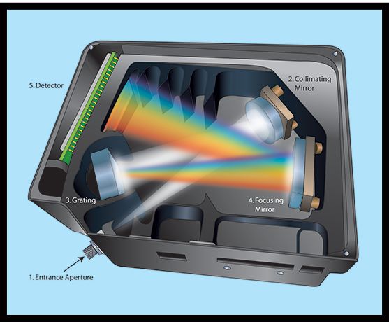
Ocean Optics spectrometers are designed to project a spectrally convolved image of the input slit plane onto the detector (Figure 1). For example, if a light source comprising three monochromatic lines is projected onto the slit (aperture), then three distinct images of the slit would be seen at the detector plane. The images would be separated from each other by an amount determined by the wavelength dispersion of the system.

Figure 1: Light enters the spectrometer at its entrance aperture.
Free Space Optics
In free space coupling, an image of the subject is projected onto the slit. The details of the image projected onto the slit do matter. For example, if the image of a circular object is projected and greatly de-magnified onto the slit, the image of the object may be lesser in size than the slit and produce an effect similar to having a fiber smaller than the slit. In this case, the experimenter has to be careful with horizontal alignment of the image projected onto the slit. Horizontal shift will appear as a peak wavelength shift; however, the shift can never exceed the slit's original FWHM (full width at half maximum, an expression of spectrometer resolution).
Moving the image vertically from the center of the slit will cause the apparent amplitude to change. Light entering the vertical center of the slit is most efficiently coupled through the system. Light entering at the top or bottom of the slit will not be routed to the detector as efficiently.
Also, changing the angle of input causes the apparent intensity to change due to vignetting in the spectrometer. Light entering at 0° to the normal has the highest efficiency. To minimize these effects, ensure that the horizontal and vertical offsets, as well as horizontal and vertical angles, are fixed throughout the experiment.
All of these alignment issues are greatly reduced if the projected image overfills the slit and overfills the numerical aperture of the spectrometer. This spatial and angular overfilling allows small angle changes and small offset changes to be irrelevant. If the image projected onto the slit plane is not properly focused then the field of view is not a well-defined region and will instead have fuzzy edges.
SMA Bulkhead
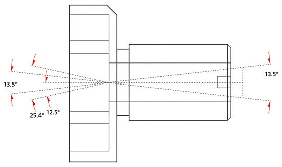
The SMA bulkhead has an aperture that has been sized to restrict the angle of light entering the spectrometer (Figure 2). This has been designed to optimally fill the optical elements without overfilling, which would increase stray light. The full angle defined by a ray from the slit to the aperture is roughly 13.5°. The full angle defined by a ray from the opening of the SMA to the slit is greater than the 13.5°. This means that in a free space optical setup that is properly focused on the slit, the SMA connector is not restricting any light.

Figure 2: An aperture in the spectrometer's SMA bulkhead restricts the angle of light entering the bench.
Ocean Optics
830 Douglas Avenue, Dunedin FL 34698
tel. +1 727-733-2447
Website: www.OceanOptics.com


