Maxwell's Equations, Part III
Here's the fundamental calculus you need to understand Maxwell's first equation

This is the third part of a multipart series on Maxwell's equations of electromagnetism. The discussion leading up to the first equation got so long that we had to separate it into two parts. However, the ultimate goal of the series is a definitive explanation of these four equations; readers will be left to judge how definitive it is. As a reminder, figures are being numbered sequentially throughout this series, which is why the first figure in this column is Figure 16. I hope this does not cause confusion. Another note: this is going to get a bit mathematical. It can't be helped: models of the physical universe, like Newton's second law F = ma, are based in math. So are Maxwell's equations.
In the previous installment, we started introducing the concepts of slope and discussed how calculus deals with slopes of curved lines. Here, we'll start with calculus again, with our ultimate goal being the understanding of Maxwell's first equation.
More Advanced Calculus
We have already discussed the derivative, which is a determination of the slope of a function (straight or curved). The other fundamental operation in calculus is integration, whose representation is called an integral:

where the symbol ∫ is called the integral sign and represents the integration operation; f(x) is called the integrand and is the function to be integrated; dx is the infinitesimal of the dimension of the function; and a and b are the limits between which the integral is numerically evaluated, if it is to be numerically evaluated. (If the integral sign looks like an elongated "s", it should — Leibniz, one of the cofounders of calculus [with Newton], adopted it in 1675 to represent "sum", since an integral is a limit of a sum.) A statement called the fundamental theorem of calculus establishes that integration and differentiation are the opposites of each other, a concept that allows us to calculate the numerical value of an integral. For details of the fundamental theorem of calculus, consult a calculus text. For our purposes, all we need to know is that the two are related and calculable.

Figure 16: The geometric interpretation of a simple integral is the area under a function and bounded on the bottom by the x-axis (that is, y = 0). (a) For the function f(x) = x, the areas as calculated by geometry and integration are equal. (b) For the function f(x) = x2, the approximation from geometry is not a good value for the area under the function. A series of rectangles can be used to approximate the area under the curve, but in the limit of an infinite number of infinitesimally-narrow rectangles, the area is equal to the integral.
The most simple geometric representation of an integral is that it represents the area under the curve given by f(x) between the limits a and b and bound by the x axis. Look, for example, at Figure 16a. It is a figure of the line y = x or, in more general terms, f(x) = x. What is the area under this function but above the x axis, shaded gray in Figure 16a? Simple geometry indicates that the area is ½ units — the box defined by x = 1 and y = 1 is 1 unit (1 × 1), and the right triangle that is shaded gray is one-half of that total area, or ½ unit in area. Integration of the function f(x) = x gives us the same answer. The rules of integration will not be discussed here; it is assumed that the reader can perform simple integration:

It is a bit messier if the function is more complicated. But, as first demonstrated by Reimann in the 1850s, the area can be calculated geometrically for any function in one variable (easy to visualize, but in theory this can be extended to any number of dimensions) by using rectangles of progressively narrower widths, until the area becomes a limiting value as the number of rectangles goes to infinity and the width of each rectangle gets infinitely narrow — one reason a good calculus course begins with a study of infinite sums and limits! But I digress. For the function in Figure 16b, which is f(x) = x2 , the area under the curve, now poorly approximated by the shaded triangle, is calculated exactly with an integral:

As with differentiation, integration can also be extended to functions of more than one variable. The issue to understand is that when considering functions, the space you need to use has one more dimension than variables because the function needs to be plotted in its own dimension. Thus, a plot of a one-variable function requires two dimensions, one to represent the variable and one to represent the value of the function. Figures 9 and 10 in the previous installment (1) are therefore two-dimensional plots. A two-variable function needs to be plotted or visualized in three dimensions, like Figures 11 or 12 in the previous column. Looking at the two-variable function in Figure 17, we see a line across the function's values, with its projection in the (x,y) plane. The line on the surface is parallel to the y axis, so it is showing the trend of the function only as the variable x changes. If we were to integrate this multivariable function with respect only to x (in this case), we would be evaluating the integral only along this line, called a line integral. One interpretation of this integral would be that it is simply the part of the volume under the overall surface that is beneath the given line; that is, it is the area under the line.
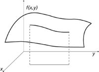
Figure 17: A multivariable function f(x,y) with a line paralleling the y axis.
If the surface represented in Figure 17 represents a field (either scalar or vector), then the line integral represents the total effect of that field along the given line. The formula for calculating the "total effect" might be unusual, but it makes sense if we start from the beginning. Consider a path whose position is defined by an equation P, which is a function of one or more variables. What is the distance of the path? One way of calculating the distance s is velocity v times time t, or

But velocity is the derivative of position P with respect to time, or dP/dt. Let us represent this derivative as P'. Our equation becomes

This is for finite values of distance and time, and for that matter, for constant P'. (For example: total distance at 2.0 m/s for 4.0 s = 2.0 m/s × 4.0 s = 8.0 m. In this example, P' is 2.0 m/s and t is 4.0 s.) For infinitesimal values of distance and time, and for a path whose value may be a function of the variable of interest (in this case, time), the infinitesimal form is

To find the total distance, we integrate between the limits of the initial position a and the final position b

The point is that it's not the path P we need to determine the line integral — it's the change in P, denoted as P'. This seems counterintuitive at first, but hopefully the above example makes the point clear. It's also a bit of overkill when one remembers that derivatives and integrals are opposites of each other: The above analysis has us determine a derivative and then take the integral, undoing our original operation, to get the answer. One might have just kept the original equation and determined the answer from there. We'll address this issue shortly. One more point: It doesn't have to be a change with respect to time. The derivative involved can be a change with respect to a spatial variable. This allows us to determine line integrals with respect to space as well as time.
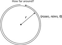
Figure 18: How far is the path around the circle? A line integral can tell us and it agrees with what basic geometry predicts (2Ïr).
Suppose the function for the path P is a vector? For example, consider a circle C in the (x,y) plane having radius r. Its vector function is C = rcosθi + rsinθj + 0k (see Figure 18), which is a function of the variable θ, the angle from the positive x axis. What is the circumference of the circle; that is, what is the path length as θ goes from 0 to 2π, the radian measure of the central angle of a circle? According to our formulation above, we need to determine the derivative of our function. But for a vector, if we want the total length of the path, we care only about the magnitude of the vector and not its direction. Thus, we'll need to derive the change in the magnitude of the vector. We start by defining the magnitude: the magnitude |m| of a three-magnitude (or lesser) vector is the Pythagorean combination of its components

For the derivative of the path/magnitude with respect to time, which is the velocity, we have

For our circle, we have the magnitude as simply the i, j, and k terms of the vector. These individual terms are also functions of θ. We have
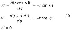
From this we have

(and we will ignore the z part, since it's just zero). For the squares of the unit vectors, we have i2 = j2 = i•i = j•j = 1. Thus, we have

We can factor out the r2 term from each term and then out of the square root to get

Because, from elementary trigonometry, sin2 θ + cos2 θ equals 1, we have

This seems like an awful lot of work to show what we all know, that the circumference of a circle is 2πr. But hopefully it will convince you of the propriety of this particular mathematical formulation.
Now, back to "total effect." For a line integral involving a field, there are two expressions we need to consider: the definition of the field F[x(q),y(q),z(q)] and the definition of the vector path p(q), where q represents the coordinate along the path. (Note that at least initially, the field F is not necessarily a vector.) In that case, the total effect s of the field along the line is given by

The integration is over the path p, which needs to be determined by the physical nature of the system of interest. Note that in the integrand, the two functions F and |p's| are multiplying together.
If F is a vector field over the vector path p(q), denoted F[p(q)], then the line integral is defined similarly

Here, we need to take the dot product of the F and p' vectors.
A line integral is an integral over one dimension that gives, effectively, the area under the function. We can perform a two-dimensional integral over the surface of a multidimensional function, as pictured in Figure 19. That is, we want to evaluate the integral

where g(x,y,z) is some scalar function on a surface S. Technically, this expression is a double integral over two variables. This is generally called a surface integral.
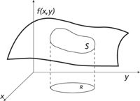
Figure 19: A surface S over which a function f(x,y) will be integrated.
The mathematical tactic for evaluating the surface integral is to project the functional value into the perpendicular plane, accounting for the variation of the function's angle with respect to the projected plane. The proper variation is the cosine function, which gives you a relative contribution of 1 if the function and the plane are parallel (for example, cos 0° = 1) and a relative contribution of 0 if the function and the plane are perpendicular (for example, cos 90° = 0). This automatically makes us think of a dot product. If the space S is being projected into the (x,y) plane, then the dot product will involve the unit vector in the z direction, or k. (If the space is projected into other planes, other unit vectors are involved, but the concept is the same.) If n(x,y,z) is the unit vector that defines the line perpendicular to the plane marked out by g(x,y,z) (called the normal vector), then the value of the surface integral is given by

where the denominator contains a dot product and the integration is over the x and y limits of the region R in the (x,y) plane of Figure 19. The dot product in the denominator is actually fairly easy to generalize. When that happens, the surface integral becomes

where f represents the function of the surface and g represents the function you are integrating over. Typically, to make g a function of only two variables, you let z = f(x,y) and substitute the expression for z into the function g, if z appears in the function g.
If, instead of a scalar function g we had a vector function F, the above equation gets a bit more complicated. In particular, we are interested in the effect that is normal to the surface of the vector function. Because we previously defined n as the vector normal to the surface, we'll use it again: We want the surface integral involving F•n, or

For a vector function F = Fxi + Fyj + Fzk and a surface given by the expression f(x,y) = z, this surface integral is

This is a bit of a mess! Is there a better, easier, more concise way of representing this?
A Better Way
There is a better way to represent this last integral, but we need to back up a bit: What exactly is F•n? Actually, it's just a dot product, but the integral

is called the flux of F. The word flux comes from the Latin word fluxus, meaning flow. For example, suppose you have some water flowing through the end of a tube, as represented in Figure 20a. If the tube is cut straight, the flow is easy to calculate from the velocity of the water (given by F) and the geometry of the tube. If you want to express the flow in terms of the mass of water flowing, you can use the density of the water as a conversion. But what if the tube isn't cut straight, as shown in Figure 20b? In this case, we need to use some more complicated geometry — vector geometry — to determine the flux. In fact, the flux is calculated using the last integral in the previous section. Therefore, flux is calculable.

Figure 20: Flux is another word for amount of flow. (a) In a tube that is cut straight, the flux can be determined from simple geometry. (b) In a tube cut at an angle, some vector mathematics is needed to determine flux.
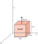
Figure 21: What is the surface integral of a cube as the cube gets infinitely small?
Consider an ideal cubic surface with the sides parallel to the axes, as shown in Figure 21, that surrounds the point (x,y,z). This cube represents our function F and we want to determine the flux of F. Ideally, the flux at any point can be determined by shrinking the cube until it gets to a single point. We will start by determining the flux for a finite-sized side, then take the limit of the flux as the size of the side goes to zero. If we look at the top surface, which is parallel to the (x,y) plane, it should be obvious that the normal vector is the same as the k vector. For this surface by itself, the flux is then

If F is a vector function, its dot product with k eliminates the i and j parts (since i•k = j•k = 0) and only the z-component of F remains. Thus, the integral above is just

If we assume that the function Fz has some average value on that top surface, then the flux is simply that average value times the area of the surface, which we will propose is equal to Δx•Δy. We need to note, though, that the top surface isn't located at z (the center of the cube), but at z + Δz/2. Therefore, we have for the flux at the top surface

where the symbol � means "approximately equal to." It will become "equal to" when the surface area shrinks to zero.
The flux of F on the bottom side is exactly the same except for two small changes. First, the normal vector is now –k, so there is a negative sign on the expression. Second, the bottom surface is lower than the center point, so the function is evaluated at z – Δz/2. Thus, we have

The total flux through these two parallel planes is the sum of the two expressions

We can factor the ΔxΔy out of both expressions. Now, if we multiply this expression by Δz/Δz (which equals 1), we have

We rearrange:

and recognize that ΔxΔyΔz is the change in volume of the cube, ΔV:

As the cube shrinks, Δz approaches zero. In the limit of infinitesimal change in z, the first term in the product above is simply the definition of the derivative of Fz with respect to z! Of course, it's a partial derivative, because F depends on all three variables, but we can write the flux more simply as

A similar analysis can be performed for the two sets of parallel planes; only the dimension labels will change. We ultimately get

(Of course, as Δx, Δy, and Δz go to zero, so does ΔV, but this doesn't affect our end result.) The expression in the parentheses above is so useful that it is defined as the divergence of the vector function F:

Because divergence of a function is defined at a point and the flux (two equations above) is defined in terms of a finite volume, we can also define the divergence as the limit as volume goes to zero of the flux density (defined as flux divided by volume):

There are two abbreviations to indicate the divergence of a vector function. One is to simply use the abbreviation "div" to represent divergence:

The other way to represent the divergence is with a special function. The function ∇ (called "del") is defined as

If one were to take the dot product between ∇ and F, we would get the following result:

which is the divergence! Note that, although we expect to get nine terms in the dot product above, cross terms between the unit vectors (like i•k or k•j) all equal zero and cancel out, while like terms (that is, j•j) all equal 1 because the angle between a vector and itself is zero and cos 0 = 1. As such, our nine-term expansion collapses to only three nonzero terms. Alternately, one can think of the dot product in terms of its other definition:

where a1, a2, and so forth are the scalar magnitudes in the x, y, etc., directions. So, the divergence of a vector function F is indicated by
What does the divergence of a function mean? First, note that the divergence is a scalar, not a vector, field. No unit vectors remain in the expression for the divergence. This is not to imply that the divergence is a constant — it may in fact be a mathematical expression whose value varies in space. For example, for the field

the divergence is

which is a scalar function. Thus, the divergence changes with position.
Divergence is an indication of how quickly a vector field spreads out at any given point; that is, how fast it diverges. Consider the vector field

which we originally showed in Figure 13 of the last column and are reshowing in Figure 22. It has a constant divergence of 2 (easily verified), indicating a constant "spreading out" over the plane. However, for the field

whose divergence is 2x, the vectors get farther and farther apart as x increases (see Figure 23).
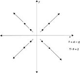
Figure 22: The divergence of the vector field F = xi + yj is 2, indicating a constant divergence, a constant spreading out, of the field at any point in the (x,y) plane.
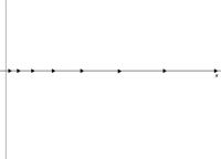
Figure 23: A nonconstant divergence is illustrated by this one-dimensional field F = x2 i whose divergence is equal to 2x. The arrowheads represent length of the vector field at values of x = 1, 2, 3, 4, and so forth. The greater the value of x, the farther apart the vectors get - that is, the greater the divergence.

Figure 24: It is an experimental fact that charges exert forces on each other. That fact is modeled by Coulomb’s law.
Maxwell's First Equation
If two electric charges were placed in space near each other, as is shown in Figure 24, there would be a force of attraction between the two charges. The charge on the left would exert a force on the charge on the right, and vice versa. That experimental fact is modeled mathematically by Coulomb's law, in which a vector form is

where q1 and q2 are the magnitudes of the charges (in elementary units, where the elementary unit is equal to the charge on the electron) and r is the scalar distance between the two charges. The unit vector r represents the line between the two charges q1 and q2. The modern version of Coulomb's law includes a conversion factor between charge units (coulombs, C) and force units (newtons, N), and is written as

where ε0 is called the permittivity of free space and has an approximate value of 8.854... ×10-12 C2 /Nm2 .
How does a charge cause a force to be felt by another charge? Michael Faraday suggested that a charge had an effect in the surrounding space called an electric field, a vector field, labeled E. The electric field is defined as the Coulombic force felt by another charge divided by the magnitude of the original charge, which we will choose to be q2:

where in the second expression we have substituted the expression for F. Note that E is a vector field (as indicated by the bold-faced letter) and is dependent on the distance from the original charge. E also has a unit vector that is defined as the line between the two charges involved, but in this case the second charge has yet to be positioned, so in general E can be thought of as a spherical field about the charge q1. The unit for an electric field is newton per coulomb, or N/C.
Because E is a field, we can pretend it has flux — that is, something is "flowing" through any surface that encloses the original charge. What is flowing? It doesn't matter; all that matters is that we can define the flux mathematically. In fact, we can use the definition of flux given earlier. The electric flux Φ is given by

which is perfectly analogous to our previous definition of flux.
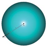
Figure 25: A charge in the center of a spherical shell with radius r has a normal unit vector equal to r, in the radial direction and with unit length, at any point on the surface of the sphere.
Let us consider a spherical surface around our original charge that has some constant radius r. The normal unit vector n is simply r, the radius unit vector, since the radius unit vector is perpendicular to the spherical surface at any of its points (Figure 25). Because we know the definition of E from Coulomb's law, we can substitute into the expression for electric flux

The dot product r•r is simply 1, so this becomes

If the charge q1 is constant, 4 is constant, π is constant, the radius r is constant, and the permittivity of free space is constant, these can all be removed from the integral to get

What is this integral? Well, we defined our system as a sphere, so the surface integral above is the surface area of a sphere. The surface area of a sphere is known: 4πr2 . Thus, we have

The 4, the π, and the r2 terms cancel. We are left with

Recall, however, that we previously defined the divergence of a vector function as

Note that the integral in the definition has exactly the same form as the electric field flux Φ. Therefore, in terms of the divergence, we have for E

where we have made the appropriate substitutions to get the final expression. We will rewrite this last expression as

The expression q1 /ΔV is simply the charge density at a point, which we will define as ρ. This last expression simply becomes

This equation is Maxwell's first equation of electromagnetism. It is also written as

Maxwell's first equation is also called Gauss' law, after Carl Friedrich Gauss, the German polymath who first determined it but did not publish it. (It was finally published in 1867 after his death by his colleague William Weber; Gauss had a habit of not publishing much of his work, and his many contributions to science and mathematics were only realized posthumously.)
In the next installment, we will expand on our discussion by looking at Maxwell's second equation. In that case, we will be concerned with our old friend magnetism.
David W. Ball is normally a professor of chemistry at Cleveland State University in Ohio. For a while, though, things will not be normal: starting in July 2011 and for the commencing academic year, David will be serving as Distinguished Visiting Professor at the United States Air Force Academy in Colorado Springs, Colorado, where he will be teaching chemistry to Air Force cadets. He still, however, has two books on spectroscopy available through SPIE Press, and just recently published two new textbooks with Flat World Knowledge. Despite his relocation, he still can be contacted at d.ball@csuohio.edu. And finally, while at USAFA he will still be working on this series, destined to become another book at an SPIE Press web page near you.

David W. Ball
References
(1) D.W. Ball, Spectroscopy 26(6), 14–21 (2011).
(2) B. Baigrie, Electricity and Magnetism (Greenwood Press, Westport, Connecticut, 2007).
(3) D. Halliday, R. Resnick, and J. Walker, Fundamentals of Physics 6th Ed. (John Wiley and Sons, New York, New York, 2001).
(4) J.E. Marsden and A.J. Tromba, Vector Calculus 2nd Ed. (W. H. Freeman and Company, 1981).
(5) H.M. Schey, Div, Grad, Curl, and All That: An Informal Text on Vector Calculus 4th Ed. (W. W. Norton and Company, New York, New York, 2005).

New Study Provides Insights into Chiral Smectic Phases
March 31st 2025Researchers from the Institute of Nuclear Physics Polish Academy of Sciences have unveiled new insights into the molecular arrangement of the 7HH6 compound’s smectic phases using X-ray diffraction (XRD) and infrared (IR) spectroscopy.
Best of the Week: Multidimensional Mass Spectrometry, Exoplanet Discovery, LIBS Plasma Behavior
March 28th 2025Top articles published this week include a long-form video interview from the American Academy of Forensic Sciences (AAFS) Conference, as well as several news articles highlighting studies where spectroscopy is being used to advance space exploration.