Spectral Resolution and Dispersion in Raman Spectroscopy
A Raman spectrometer’s spectral resolution is determined by its spectral dispersion in conjunction with the entrance slit width. We explain the instrument design parameters involved.
Questions often arise regarding the spectral resolution required to perform Raman spectroscopy and those components of the spectrometer that contribute toward it. The spectral resolution required will depend on the materials you are working with, their natural bandwidths, and the degree to which you need to measure a peak shift or resolve two closely spaced peaks. A Raman spectrometer’s spectral resolution is determined by its spectral dispersion in conjunction with the entrance slit width. The spectral dispersion depends on the following four items: the spectrometer’s focal length, the grating groove density, the individual pixel width in the array detector, and the absolute wavelength of the Raman scattered light striking the detector. Here, we discuss how each of these items affects the spectral dispersion and ultimately the spectral resolution.
It is quite common to hear a colleague ask what spectral resolution is required of a spectrometer to perform Raman spectroscopy. The answer depends on the materials the spectroscopist is working with and the questions that need to be resolved. Are the materials solids, liquids, or gases? If they are solids, the natural bandwidths of the amorphous materials are significantly greater than those of crystalline compounds or elements. In liquids, molecular interactions such as hydrogen bonding can induce significant broadening of Raman bands as a result of a greater distribution of the vibrational energy states. For gases, they generally have weak molecular interactions, and therefore tend to have sharp and narrow Raman bands. Generally, the narrower the Raman bands of the material that one is studying, the greater the spectral resolution required to perform the analysis.
In addition to the phase (solid, liquid, or gas) of the material being studied, other considerations related to spectral resolution are the material characteristic to be analyzed and the question that needs to be answered. For example, Raman spectroscopy has been used to characterize the stress on a material and the strain induced in it (1). Stress is a force per unit area applied to an object, and strain is the effect on the object resulting from the stress. Specifically, strain is the change in the positions of the atoms or the lengths of the chemical bonds within the object induced by the application of stress. Compressive and tensile stresses will induce corresponding strains in the crystal that can be observed as shifts of a Raman peak position to higher or lower frequencies respectively. The magnitude of the Raman peak shift will be commensurate with that of the stress and corresponding strain induced in the material. If one is studying the strain induced in a material by the application of a stress, then the required spectral resolution will be dictated by the resolution of the strain one wishes to determine, and the degree to which a Raman peak position changes with strain.
Raman spectroscopy is often found to be experimentally more convenient to use than X-ray diffraction for crystal polymorph characterization or screening (2). Raman spectra of a compound’s polymorphs can be reliably used to confirm crystal forms, or even identify new ones in a research setting or in polymorph screening. The most important aspect of Raman spectroscopy when applying it to polymorph analysis is spectral resolution. That is consistent with the fact that high spectral resolution is also required to differentiate crystal forms by X-ray diffraction. The Raman spectrometer must have the spectral resolution sufficient to resolve the smallest differences in energies of the crystal lattice vibrational modes; these are affected by changes in molecular interactions arising from different unit cell structures or configurations of the molecules or formula units within the unit cell. Just as small differences in a compound’s crystal structure lead to small differences in the X-ray diffraction pattern, the Raman spectra of crystals with small differences in bond lengths or crystal spacing will manifest small differences in the Raman peak positions. Therefore, just as high-resolution X-ray diffraction is needed to resolve polymorphs, so, too, is high spectral resolution required to differentiate crystal forms by Raman spectroscopy.
Spectral Dispersion
Raman spectrometers are fundamentally wavelength analyzers designed to transmit and disperse the Raman scattered light collected from a sample while blocking the intense reflected or scattered laser light. Historically, spectrometer designs were based on double and triple monochromators to prevent laser light from reaching that stage of the spectrometer where the weak Raman scattered light was spectrally dispersed and detected. Allowing the laser light to reach the final stage of the spectrometer was problematic insofar as it could generate stray light as well as saturate or damage the detector. Stray laser light is light that strikes the detector at locations not corresponding to its actual wavelength. Therefore, peaks can appear at a Raman shift in the spectrum, even though the origin of the signal is reflected or scattered laser light. The development of optical notch filters with strong light rejection of the laser wavelength but with high transmission of longer wavelengths has led to the widespread use of single grating spectrographs for Raman spectroscopy. The spectograph’s function is then to separate or disperse by wavelength the light that has passed through the filter onto a detector to generate a Raman spectrum. An excellent resource for understanding Raman spectrometers, their components, and how their designs contribute to spectral dispersion and resolution can be found in chapter eight of Richard McCreery’s book titled Raman Spectroscopy for Chemical Analysis (3).
A schematic diagram of a single grating Czerny-Turner spectrograph is shown in Figure 1. Each of the components and the design of the spectrograph contribute to its performance, particularly with its spectral dispersion and resolution. We discuss in the next section how the width of the entrance slit in conjunction with the spectral dispersion directly affects the spectral resolution of the spectrometer.
Figure 1: Schematic diagram of a Czerny-Turner (C-T) spectrograph.
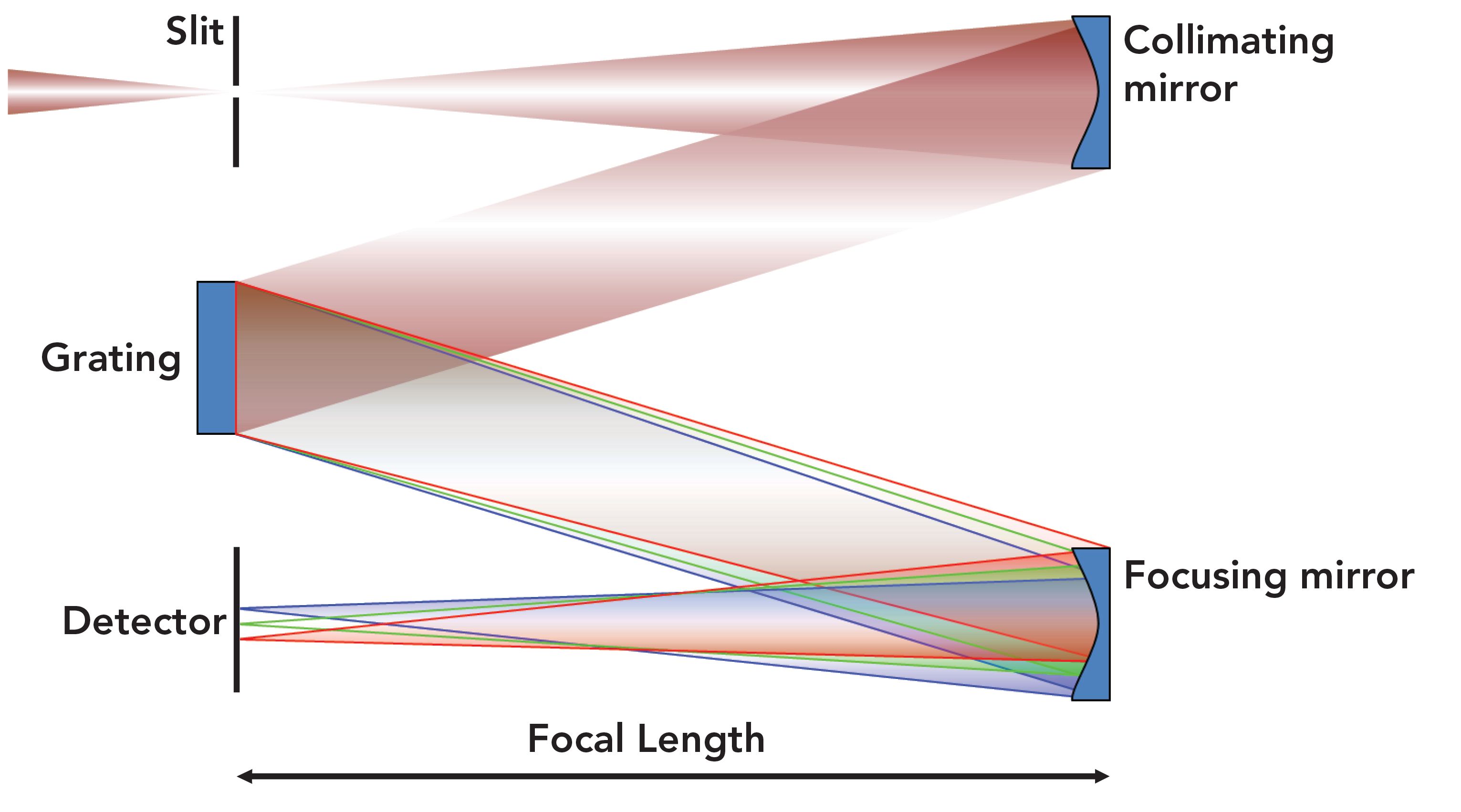
The light collected from the sample is focused onto the entrance slit. After passing through the slit, the light diverges and strikes a collimating mirror. The reflected collimated light is then directed onto a diffraction grating, whereupon the light is dispersed with respect to wavelength. Upon diffraction by the grating, the light reflects off of the focusing mirror, where it is brought to a focus, albeit dispersed by a wavelength in the focal plane. The groove density of the grating in conjunction with the focal length of the spectrometer determines the dispersion (dλ/dl) or spread of the wavelengths (λ) with respect to distance (l) at the focal plane where the detector is positioned. In years past, Raman spectrometers typically had an exit slit at the focal plane, and a single channel detector such as a photomultiplier tube. Today, a multichannel detector such as a charge-coupled device (CCD) is used and placed at the focal plane of the focusing mirror. The individual CCD pixel can be thought of as comparable to the exit slit. The pixel width then physically corresponds to the dl of the wavelength spectral dispersion dλ/dl when the dispersion is reported in units of nm/pixel.
The light diffracted from a grating is dispersed almost linearly in wavelength; that is, dλ/dl is a fairly constant value over a limited wavelength range dependent on grating groove density, diffraction order and angle, and focal length of the focusing mirror. However, the Raman spectrum is plotted as a function of wavenumber (ṽ) shift relative to the absolute wavenumber of the laser, which is equal to the reciprocal of the wavelength 1/λ. Therefore, the spectral dispersion in wavenumber and not wavelength is relevant and important to the Raman spectroscopist. The derivative of the wavenumber with respect to wavelength (dṽ/dλ) is equal to -1/ λ2, which is equal to -ṽ2. Therefore, the diffraction grating wavenumber dispersion (dṽ/dl) is nonlinear as a function of wavelength, and will depend upon the absolute wavelength of light at which the Raman scattering appears. That means that the spectral dispersion, and therefore the spectral resolution, will vary throughout the Raman spectrum. Logarithmic plots of the wavenumber spectral dispersion in units of cm1/pixel as a function of wavelength at the focal plane of an 800 mm focal length spectrograph with 26 µm pixel width for different grating groove densities are shown in Figure 2.
Figure 2: Logarithmic plots of spectral dispersion of an 800 mm focal length spectrograph as a function of wavelength for different grating groove densities: 300 gr/mm (green), 600 gr/mm (blue), and 1800 gr/mm (red).
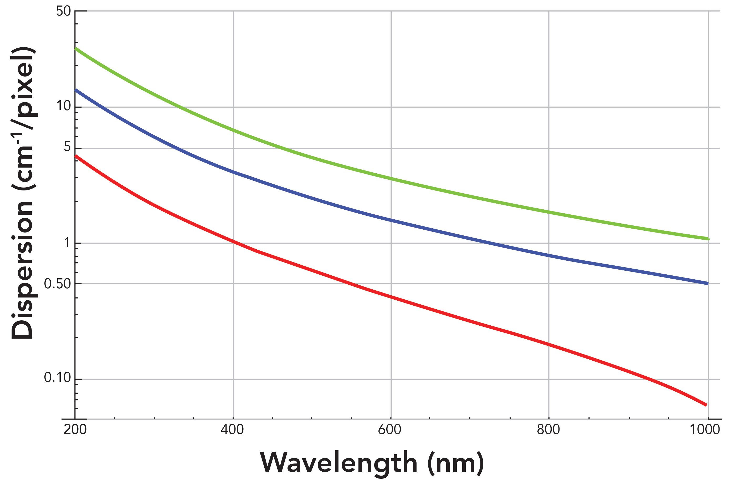
The wavenumber spectral dispersions vary substantially by as much as three orders of magnitude over the wavelength range of 200 to 1000 nm. This is among the 1800, 600, and 300 grooves per millimeter (gr/mm) gratings. Therefore, a comparison of the spectral dispersion performances of the gratings is best achieved by plotting the dispersion logarithmically as a function of wavelength. The limits of wavenumber spectral dispersion afforded by these three gratings for an 800 mm focal length spectrometer range from 26.88 cm-1/pixel at 200 nm for the 300 gr/mm grating to 0.06 cm-1/pixel at 1000 nm for the 1800 gr/mm grating. What is important to note about these wavenumber dispersion values is that a smaller value in cm-1pixel corresponds to a greater spectral dispersion. The set of 1800, 600, and 300 gr/mm gratings in conjunction with an 800 mm focal length offers the spectroscopist a wide range of spectral dispersion values with which to work. And as stated above, the dispersion values will not be constant over the entire Raman spectrum. Therefore, the choice of grating by the spectroscopist will be dictated by the excitation wavelength used, and the spectral dispersion and resolution required by the analysis of a portion of or the entire Raman spectrum. The clear trend for all diffraction gratings is that a longer excitation wavelength will generate Raman spectra with greater spectral dispersion, and therefore better spectral resolution for a given grating.
Sometimes, people think only of the grating groove density when comparing the spectral dispersion and resolution of different spectrometers. In Figure 2, the focal length is fixed at 800 mm, and we see the effect of grating groove density on the spectral dispersion. However, it needs to be understood that the dispersion achieved depends on both the grating groove density and the focal length of the spectrometer. Now, we calculate the spectral dispersion for a single grating at different focal lengths. Logarithmic plots of the wavenumber spectral dispersion in units of cm-1/pixel as a function of wavelength at the focal plane of a spectrograph with an 1800 gr/mm grating and 26 µm pixel width for focal lengths of 200, 460, and 800 mm are shown in Figure 3. The spectral dispersion at 200 nm is 17.40 and 4.35 cm-1/pixel for focal lengths of 200 and 800 mm, respectively. The dispersion value at 200 nm is four times greater for a focal length of 800 mm than that of a 200 mm focal length. Remember, the smaller the value in cm-1/pixel, the greater the spectral dispersion is. The difference in dispersion values between focal lengths remains fairly constant with respect to wavelength. The spectral dispersion at 1000 nm is 0.25 and 0.06 cm1/pixel for focal lengths of 200 and 800 mm, respectively. Those values differ by a factor of 4.2. The key takeaway here is that the wavenumber spectral dispersion for a given grating will vary linearly and improve with greater focal length.
Figure 3: Logarithmic plots of spectral dispersion of a spectrograph with an 1800 gr/mm grating as a function of wavelength for different focal lengths: 200 mm (green), 460 mm (blue), and 800 mm (red).
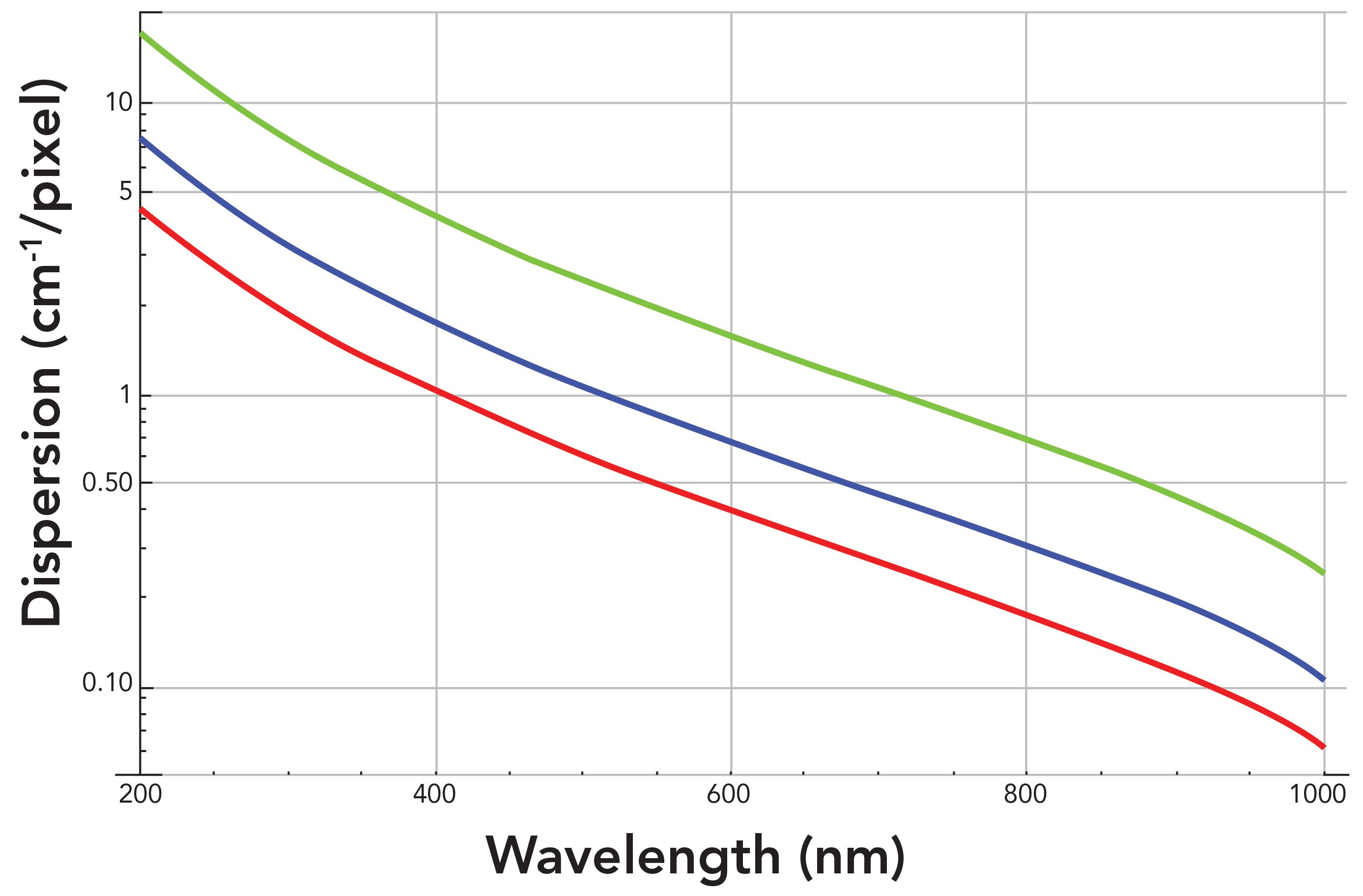
Another important characteristic related to spectral dispersion is spectral coverage. The spectral range from the lowest Raman shift to the highest Raman shift can be detected by one position of the grating for a given focal length and CCD detector width. In particular, the greater the spectral dispersion is (smaller value of cm-1 pixel), the smaller the spectral coverage will be. This is easy to understand since the CCD detector has a fixed number of pixels and total width. For high spectral dispersion, each pixel will have a small value of cm-cm-1/pixel, and the spectral coverage will be equal to that value times the number of pixels in a single row of the CCD. Therefore, the spectral coverage will decrease as the values of wavenumber spectral dispersion in units of cm-1 pixel decrease. So, in considering the reduction in spectral dispersion values as a function of wavelength as shown in Figures 2 and 3, we can understand why the spectral coverage decreases with increasing excitation wavelength. Also, the spectral coverage will decrease as the grating is positioned at longer wavelengths to cover higher wavenumber portions of the Raman spectrum.
To better grasp the relationship between grating groove density, focal length, spectral coverage, and wavenumber spectral dispersion (dṽ/dl) at several Raman shift frequencies, see the values listed in Table I. The examples given are for two of the more commonly used laser excitation wavelengths, 532 nm and 632.8 nm. Spectral coverage and dispersion values are shown for four gratings and for the shortest (200 mm) and longest (800 mm) focal lengths of commonly used Raman spectrometers. Note that the spectral coverage is greatest (7060.49 cm-1) and the dispersion least (7.34 cm-1/pixel at Raman shift of 100 cm-1) for the lowest groove density grating (600 gr/mm) and shortest focal length (200 mm) using 532 nm excitation. When using 633 nm excitation with the same grating and focal length, the spectral coverage is significantly less at 4778.68 cm-1 and the dispersion at Raman shift of 100 cm-1 is greater with a lesser value of 5.13 cm-1/pixel. This comparison demonstrates that the spectral coverage will decrease and dispersion become greater (smaller values in cm-1/pixel) when using longer excitation wavelengths for a given grating groove density and focal length.
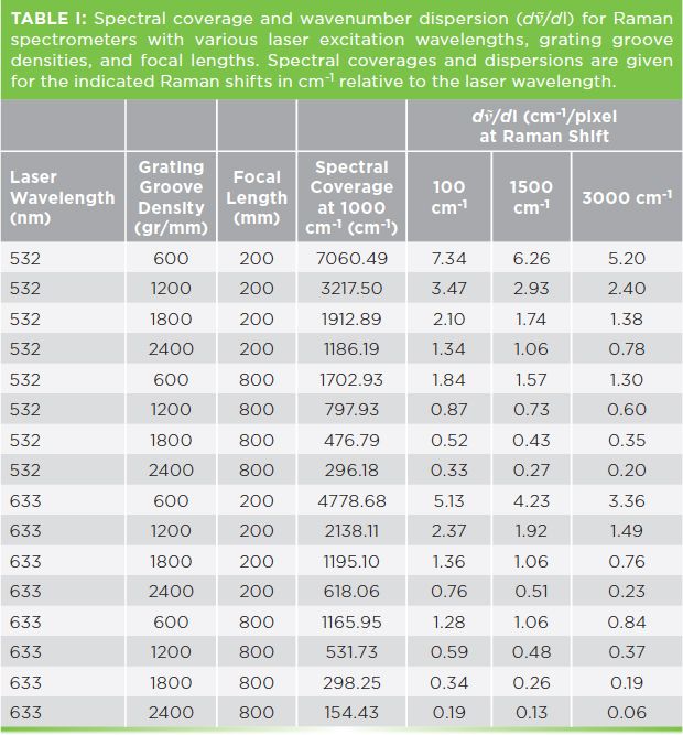
There are some additional patterns that we can observe from the progression of values listed in Table I. The first progression to note is that the spectral coverage decreases and dispersion increases (smaller values in cm-1/pixel) as the grating groove density increases with a fixed focal length. A spectrometer will normally have a fixed focal length; therefore, the spectral coverage and dispersion that is obtained is dictated by the groove density of the grating that is selected. Having data such as those shown in Table I will help you choose the right combination of excitation wavelength and grating to achieve the spectral coverage and dispersion required for your work. The dispersion values for different Raman shifts listed in Table I clearly demonstrate how they can vary throughout the spectrum. In all cases, the spectral dispersion will always be less at low frequencies compared to those in the CH stretching frequency region near 3000 cm-1. Therefore, a grating with spectral dispersion suitable for that portion of the spectrum, where either the spectral resolution of two closely spaced bands or a small shift of one band is important, should be selected. The range of spectral dispersion shown in Table I is substantial, and goes from 7.34 cm1 to 0.06 cm-1. Therefore, consider using the listed spectral dispersion values to guide you in the selection of excitation wavelength, grating groove density, and a fixed focal length to perform Raman spectroscopic work to characterize your materials.
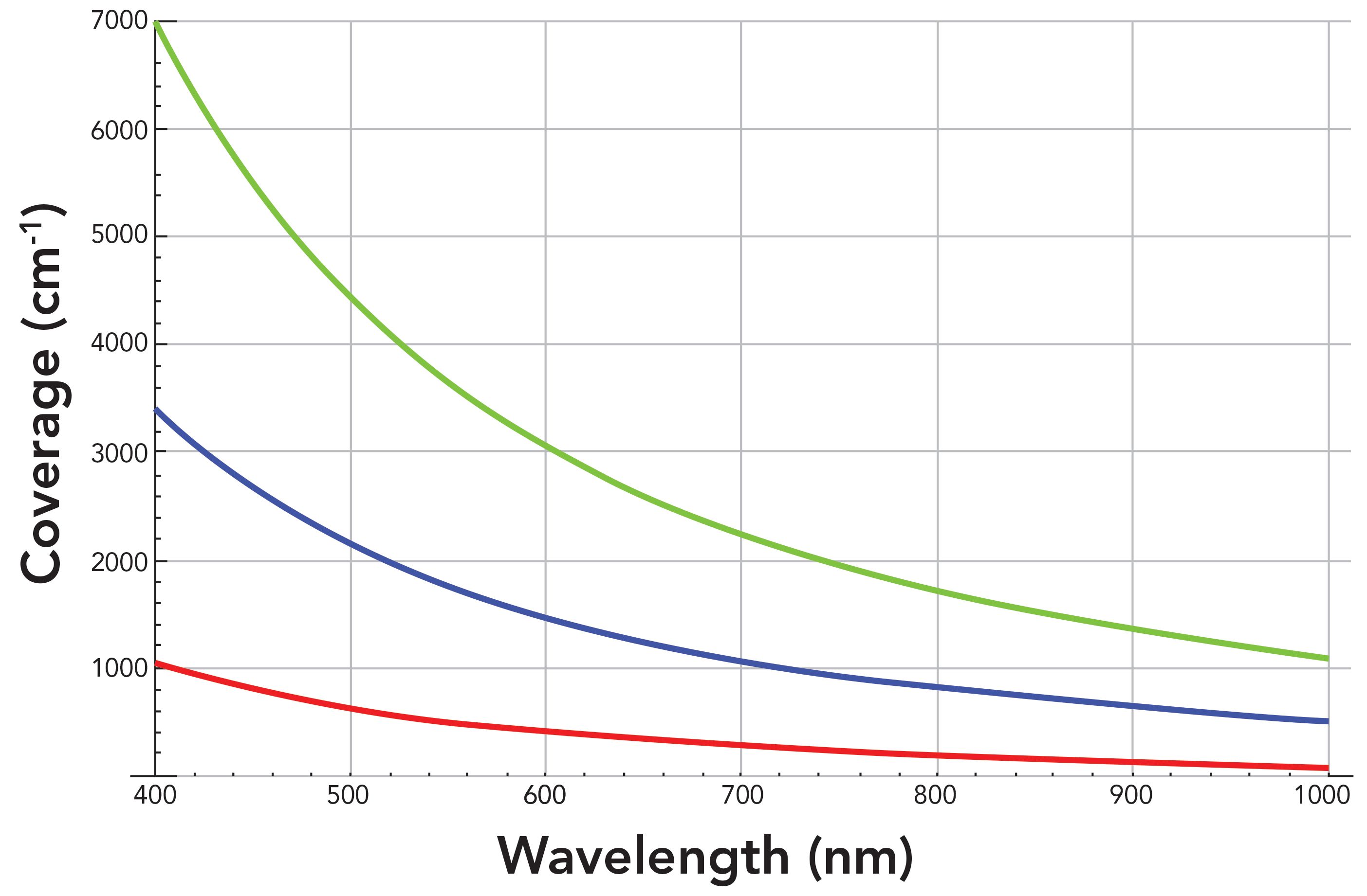
The change in spectral coverage as a function of wavelength for different grating groove densities can be seen graphically in Figure 4. The spectral coverage for a given grating and the difference in spectral coverage between two gratings at a specific wavelength both increase significantly at shorter wavelengths. This is particularly true in the ultraviolet range. Therefore, to visually appreciate the magnitude of the spectral coverage differences between gratings in a range in which most spectroscopists perform their work, the coverage is plotted over a limited wavelength range between 400 and 1000 nm. The spectral coverage plot in Figure 4 along with the specific values shown in Table I should help the Raman spectroscopist select the grating in conjunction with the focal length best suited for the work to be performed. Many Raman spectrometers include multiple gratings from which to choose for spectral acquisition. The spectral coverage along with the spectral dispersion can both be important considerations when choosing a grating for specific experiments or measurements. Spectral coverage that far exceeds the wavenumber range over which vibrational transitions occur means that signal will be measured over a spectral range with no vibrational information and with low spectral dispersion. Ultimately, the Raman spectroscopist will want to select a grating that optimizes or at least is a compromise between spectral dispersion and coverage.
Figure 4: Spectral coverage of an 800 mm focal length spectrograph as a function of wavelength for different grating groove densities: 300 gr/mm (green), 600 gr/mm (blue), and 1800 gr/mm (red).
Spectral Resolution
Thus far, we have discussed the spectral dispersion of the Raman spectrometer. Now, we advance that discussion relating the spectral dispersion to spectral resolution, which is the spectrometer performance expressed in the actual Raman spectrum. Here I quote at length the definition of spectral resolution from the book by Wilfried Neumann, containing one of the better discussions and presentations on this topic (4):
Unlike other parameters, “resolution” is not given by a physical law; it is a definition. We can differentiate between the experimental resolution R and a grating’s resolving power Rp. Resolution is determined by the ratio of the center wavelengths λ of a pair of signals, divided by the difference Δλ between the two signals, which can be safely determined. It is possible to determine resolution if two signals of equal height and very narrow bandwidth are separated by a signal drop of 10% below maximum.
Note that Neumann is referring to a saddle between the two peaks when he refers to “a signal drop of 10% below maximum.” In other words, the deeper the saddle between the peaks, the greater the percentage below maximum. However, Neumann goes on to explain that the 10% saddle between two peaks is fine for characterizing the spectral resolution of a grating but not for a full spectrometer (4):
Looking into several applications and simulating some situations, one can see that the 10% saddle is just not enough. More application-oriented manufacturers apply a saddle of 50% to define resolution, which is a good number.
Another way of stating this is that the spectral resolution R = λ/Δλ, where λ is the saddle or midpoint wavelength between the two closely spaced peaks and Δλ is the separation in wavelength between the maxima of the two peaks, can be fairly quantitated if the saddle or midpoint between the two closely spaced peaks is 50% or greater below the peaks’ maxima.
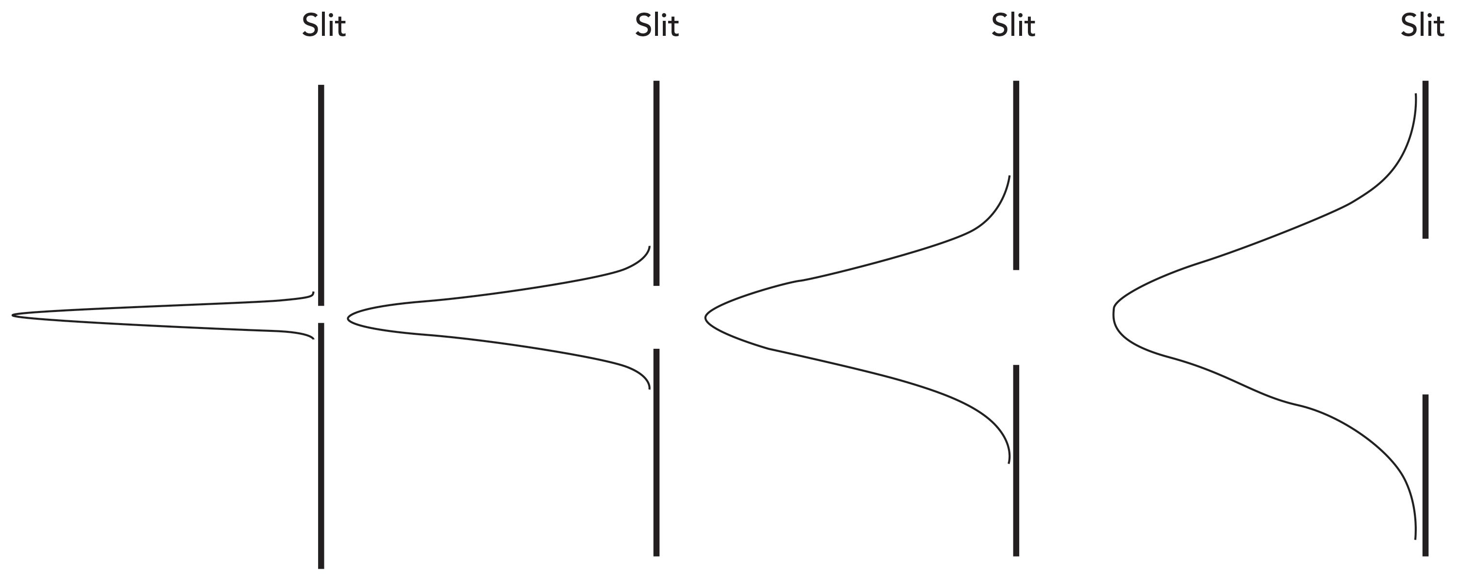
The spectral resolution as a property of the Raman spectrometer is a function of the spectral dispersion in conjunction with the spectrometer’s entrance slit. Referring back to Figure 1, the spectrometer design is such that the light collected from the sample is focused on the entrance slit. The effect of the entrance slit width on spectral band width is shown in Figure 5. The narrower the slit width is, the narrower the slit image will be at the detector focal plane. A narrower slit image corresponds to higher spectral resolution, which manifests as a lower value of peak full width at half maximum (FWHM) in cm-1. One can imagine narrowing the slit width to an extremely small value and achieving increasingly higher spectral resolution, but the value of doing so will be limited by the width of the pixel. Decreasing the slit width to obtain a spectral resolution better than the dispersion for the pixel width does not achieve that goal and only reduces the amount of light (signal) reaching the detector. Consequently, narrowing the slit width to generate a spectral image on the detector with a bandpass less than the spectral dispersion is counterproductive. This statement by Richard McCreery describes the complementarity of slit and pixel width on spectral resolution: “As a rule of thumb, the resolution is determined by the larger of the pixel width and the slit image width, multiplied by dṽ/dl” (5).
Figure 5: Diagram of the effect of entrance slit width on Raman bandwidth. The narrower the slit width is, the narrower the slit image will be at the detector focal plane yielding higher spectral resolution.
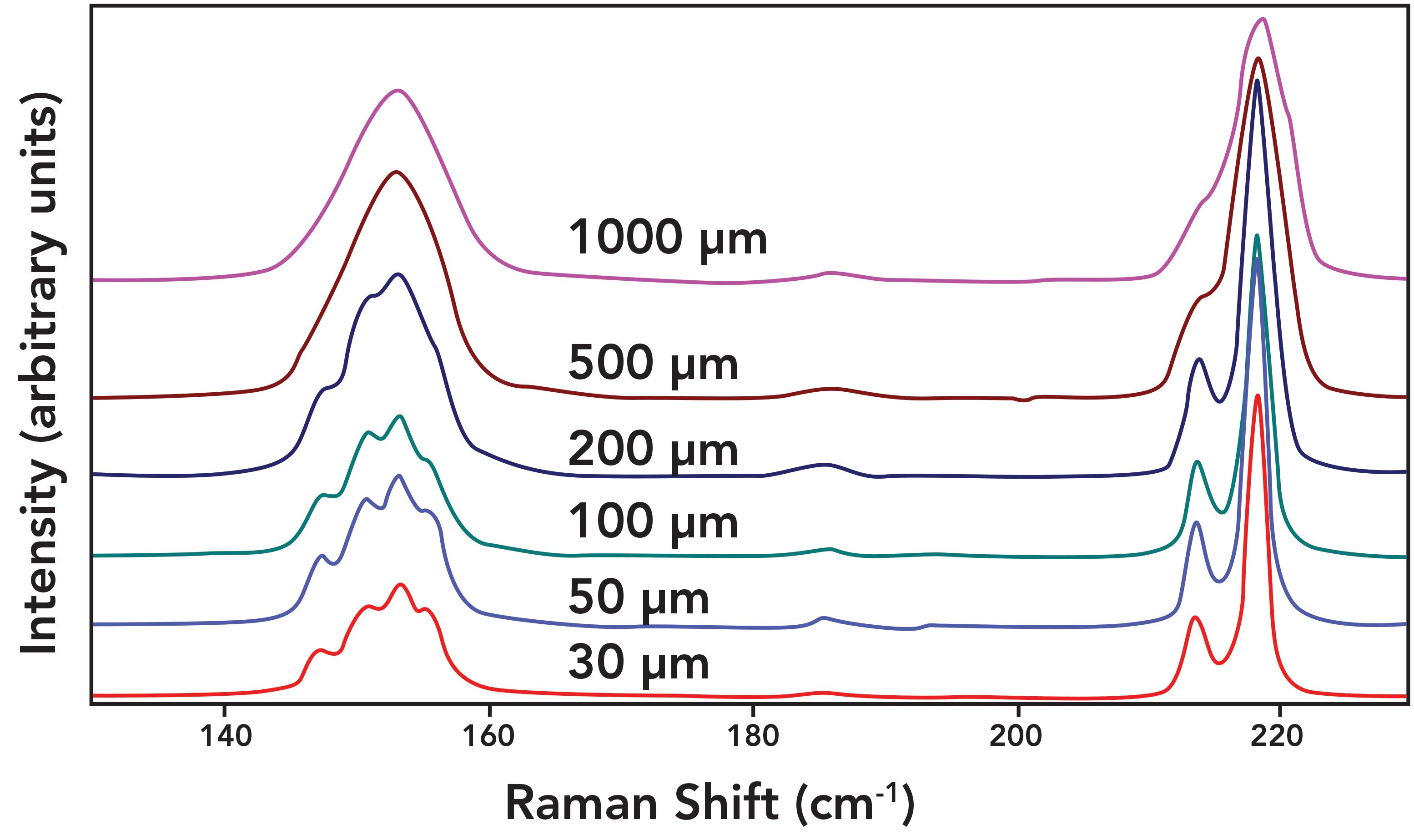
A demonstration of the effect of slit width on spectral resolution can be clearly seen in the Raman spectra of sulfur shown in Figure 6. The spectra were obtained using a 50x microscope objective to focus 632.8 nm excitation on the sample and an 1800 gr/mm grating to spectrally disperse the collected light in an 800 mm focal length spectrometer. A variable diameter circular aperture placed at the conjugate focal plane functioned as the entrance slit comparable to that depicted in Figure 1. Spectra were acquired with aperture diameters of 1000, 500, 200, 100, 50, and 30 µm. With the entrance aperture set to 1000 µm, symmetric and asymmetric peaks appear at 153 cm-1and 219 cm-1 respectively. The band at 219 cm-1 appears asymmetric because of the presence of a shoulder on the low energy side. No noticeable spectral differences appear after reducing the aperture to 500 µm, indicating that an aperture greater than 500 µm exceeds the image diameter at the conjugate focal plane where our entrance aperture is positioned. Reducing the aperture to 200 µm reveals the presence of multiple peaks convolved at the 153 cm-1 band and the shoulder of the 219 cm-1 band can now be resolved as a separate peak at 214 cm-1. Thus, the aperture at 200 µm is beginning to encroach on the focused image of the collected light. Subsequent reductions of the entrance aperture to 100, 50, and 30 µm yield increasing spectral resolution. Having said that, there is little discernible improvement of the spectral resolution in reducing the aperture from 50 to 30 µm. Therefore, using an aperture of less than 50 µm for this particular combination of microscope objective and spectrometer design will only yield a weaker signal without significantly improving spectral resolution. The important takeaway from the spectra in Figure 6 is that it is the spectral dispersion in conjunction with the entrance slit width that affects the spectral resolution observed in the Raman spectra.
Figure 6: Raman spectra of sulfur obtained with various entrance aperture diameters.
The natural bandwidths of vibrational modes in Raman spectroscopy are highly dependent on the state of the material under examination. We refer here to whether a sample is in the vapor, liquid, or solid state. Furthermore, the bandwidth of a Raman active phonon of a solid-state material will depend on whether it is amorphous or crystalline. The greater the long range translational symmetry of the solid, the narrower the Raman band will be. The state of your sample will to some degree determine the spectral resolution required for your work. Of course, molecules in the vapor phase can be expected to yield the narrowest Raman bands because the molecular interactions are very weak and therefore do not contribute to a broad distribution of vibrational energy states. Furthermore, with high spectral resolution, Raman active rotational transitions can be observed and resolved as side bands in the vibrational Raman spectrum of molecules in the vapor phase. Resolving the bands in a vibrational-rotational Raman spectrum of a gas sample is a good test of a spectrometer’s spectral resolution.
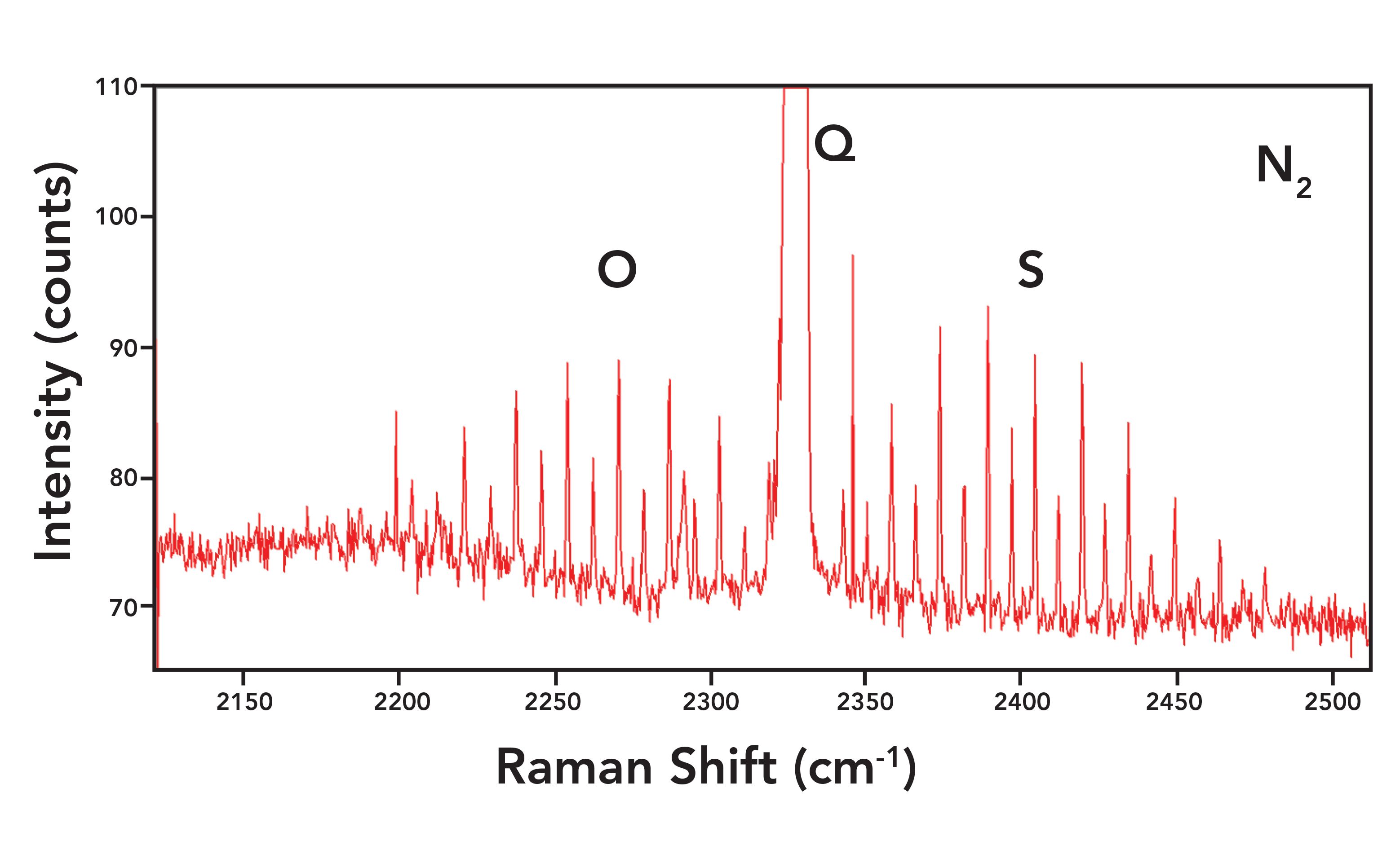
Figure 7 shows the vibrational-rotational Raman spectrum of N2 in air and in expanded view of the rotational side bands. The spectrum was obtained using a 40 mm focal length lens to focus a 532 nm laser excitation on room air and an 1800 gr/mm grating was used to spectrally disperse the collected light in an 800 mm focal length spectrometer. The entrance circular aperture functioning as a slit was 100 µm. The spectrum consists of the main vibrational symmetric stretch or Q branch at 2330.0 cm-1. The O and S rotational branches can be seen on the low and high energy sides of the Q branch, respectively. The narrow peaks on either side of the Q branch correspond to the vibrational-rotational Raman active transitions (6). The expanded intensity scale in Figure 7 reveals the alternating 2:1 intensity of the sidebands as predicted by nuclear spin statistics. The side bands are all separated by 1 J state and originate from the even and odd valued J states. Meanwhile, the intensities are all evenly distributed proportional to the populations of the original states and with respect to nuclear spin statistics. Note how narrow the N2 sidebands are with a FWHM of 0.77 cm-1.
Figure 7: Raman spectrum of nitrogen in air featuring the rotational side bands. The FWHM of the rotational sided bands is 0.77 cm-1.
Now that we have seen spectra demonstrating how the entrance slit width in conjunction with spectral dispersion affects spectral resolution, it is reasonable to ask how one might go about evaluating the spectral resolution of a spectrometer. To the best of my knowledge, there is no agreed upon method or standard material for measuring or determining the spectral resolution of a Raman spectrometer. Certainly, one way to do so would be to compare the Raman spectra obtained from a compound that yields closely spaced peaks such as sulfur in Figure 6. However, one needs to be cautious when using this comparative method with solid samples. It is vitally important that the solid-state structures of the samples be the same. Polymorphism, crystallographic defects and impurities, and crystal domain size can all lead to different natural bandwidths. If the reference samples used for comparative spectral resolution vary in any of these respects, the spectral differences could be attributed to differences in solid-state structure and not the spectral resolution of the spectrometers.
A practical alternative for evaluating spectral resolution recommended by McCreery is to measure the Raman spectrometer’s instrumental line width (7). If one were to obtain a spectrum of an infinitely narrow (monochromatic) light source, then the width of the peak that is measured constitutes the instrumental line width. The usual manner for comparing such measurements from different spectrometers is with the FWHM of the peak. A good light source for this purpose is an atomic emission lamp. McCreery states that:
The width of atomic emission lines depends on temperature and pressure, but is generally less than 0.001 nm. Thus 0.001 nm width corresponds to <0.03 cm-1 at 600 nm or 0.01 cm-1 at 1000 nm, much narrower than solid or liquid Raman bands.
Therefore, an atomic emission line approximates the infinitely narrow light source relative to the instrumental line width of the Raman spectrometer. Measuring the FWHM of atomic emission lines from a neon or mercury lamp is a good way to obtain the instrumental line width of the instrument, and comparing their FWHM values can be an effective and efficient manner of comparatively evaluating the spectral resolution of Raman spectrometers.
Conclusion
We explained the importance of a spectrometer’s spectral resolution when the Raman spectrum of a material under analysis contains closely spaced peaks. This can be important when characterizing molecular interactions, differentiating polymorphs, studying materials for stress or strain effects, and investigating compounds in the vapor phase. We discussed the difference between spectral dispersion and resolution. The spectral dispersion depends on the grating groove density, spectrometer focal length, detector pixel size, and the wavelength of light striking the detector. The greater the spectral dispersion is (smaller value of cm-1/pixel), the less the spectral coverage will be for a fixed grating position. Furthermore, the spectral coverage will decrease and dispersion become greater when using longer excitation wavelengths for a given grating groove density and focal length.
The spectral resolution was shown to be a function of the spectral dispersion in conjunction with the spectrometer’s entrance slit. The narrower the slit width is, the narrower the slit image will be at the detector focal plane. A narrower slit image corresponds to higher spectral resolution, which is manifest as a lower value of peak FWHM in cm-1. Raman spectra of sulfur and atmospheric nitrogen were shown and discussed, demonstrating how the entrance slit width in conjunction with spectral dispersion affects the spectral resolution. Methods regarding the evaluation of a spectrometer for spectral resolution were also discussed.
Acknowledgments
I would like to thank Dr. Sergey Mamedov of Horiba Scientific for the use of his Raman spectra of sulfur. I would also like to thank Dr. Michelle Sestak also of Horiba Scientific for very helpful discussions regarding spectral dispersion and resolution.
References
- D. Tuschel, Spectroscopy 34(9), 10–21 (2019).
- D. Tuschel, Spectroscopy 34(3), 10–21 (2019).
- R.L. McCreery, Raman Spectroscopy for Chemical Analysis; Wiley-Interscience: New York, New York 2000; pp 149–219.
- W. Neumann, Fundamentals of Dispersive Optical Spectroscopy Systems (SPIE Press, Bellingham, Washington, 2014), pp. 39–42.
- R.L. McCreery, Raman Spectroscopy for Chemical Analysis; Wiley-Interscience: New York, New York, 2000; pp 159.
- D. Tuschel, Spectroscopy
- (9), 14–21 (2014).
- R.L. McCreery, Raman Spectroscopy for Chemical Analysis; Wiley-Interscience: New York, New York 2000; pp 91–93.

David Tuschel is a Raman applications scientist at Horiba Scientific, in Piscataway, New Jersey, where he works with Fran Adar. David is sharing authorship of this column with Fran. He can be reached at: SpectroscopyEdit@MMHGroup.com
New Study Reveals Insights into Phenol’s Behavior in Ice
April 16th 2025A new study published in Spectrochimica Acta Part A by Dominik Heger and colleagues at Masaryk University reveals that phenol's photophysical properties change significantly when frozen, potentially enabling its breakdown by sunlight in icy environments.
Advanced Raman Spectroscopy Method Boosts Precision in Drug Component Detection
April 7th 2025Researchers in China have developed a rapid, non-destructive Raman spectroscopy method that accurately detects active components in complex drug formulations by combining advanced algorithms to eliminate noise and fluorescence interference.