Contact and Orientation Effects in FT-IR ATR Spectra
In recent years, attenuated total reflection (ATR) spectroscopy has become the preferred method for many routine infrared (IR) measurements. However, the simplicity of the technique has made it available to users who may not be aware of some effects that significantly influence the appearance of ATR spectra. This results in changes to the relative intensities of different absorption bands. The aim of this article is to explain the origin of these effects and to provide examples. In particular, it will focus on those effects that are not evident from inspection of the spectra.
In recent years, attenuated total reflection (ATR) spectroscopy has become the preferred method for many routine infrared (IR) measurements. However, the simplicity of the technique has made it available to users who may not be aware of some effects that significantly influence the appearance of ATR spectra. This results in changes to the relative intensities of different absorption bands. The aim of this article is to explain the origin of these effects and to provide examples. In particular, it will focus on those effects that are not evident from inspection of the spectra.
Recently, attenuated total reflection (ATR) spectroscopy has become the preferred method for many routine infrared (IR) measurements. The introduction of sampling accessories with small crystals greatly reduced the contact problems that had previously restricted the technique to liquids and soft solids, and the hardness and chemical resistance of diamond has made ATR an almost universal sampling method. It is generally appreciated that ATR is a surface technique and that the spectra may differ subtly from transmission spectra. However, there are less widely recognized aspects of ATR measurements of solid samples that can affect the appearance and hence the interpretation of the spectra. This article will explain the origin of these effects and illustrate them, particularly focusing on effects that are not evident from inspection of individual spectra.
The ATR Measurement
When radiation is totally reflected internally at an interface with a material of lower refractive index the electric field penetrates a short distance beyond the interface. This field, called an evanescent wave, can be absorbed by a sample on the surface (Figure 1). The electric field decreases away from the surface and the penetration depth (dp) is defined as the distance at which it falls to 1/e of its value at the surface. Penetration depth depends on the angle of incidence (θ) and the refractive indices of crystal and sample and is also proportional to the wavelength (1). For a diamond ATR element, the penetration depth at 1000 cm-1 is typically 1–2 μm. Because of the wavelength dependence, the penetration depth increases by a factor of 10 between 4000 and 400-1. In ATR measurements, the sample has to be brought sufficiently close to the surface to interact with this evanescent field. When the sample contact is perfect, the absorbance values at 1000 cm-1 are similar to those that would be observed in transmission with a pathlength of around 2–4 μm.

Figure 1: The evanescent field.
The Effects of Changing the Applied Force
Most solid samples have to be pressed into contact with the ATR crystal because of the small penetration depth. The applied force is typically adjusted to achieve chosen band intensities, with absorbances increasing as more of the sample is moved within the penetration depth. Generally, the band intensities at shorter wavelengths increase more rapidly than those at longer wavelengths. This is because material that is already contributing to the spectrum at longer wavelengths starts to contribute at shorter wavelengths as it is forced closer to the crystal. This is seen in the spectra of low density polyethylene in Figure 2. The ratio of the intensities between the C-H stretching bands at 2900 cm-1 and the CH2 rocking bands at 720 cm-1 increases to a maximum and then remains fairly constant as the applied force is increased further. In the case of very thin films the thickness may be less than the penetration depth at long wavelengths and thereby limit the band intensities.
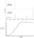
Figure 2: Spectra of LDPE at different applied forces.
Increasing the applied force may introduce other changes than those resulting from increased penetration. In polyethylene the increased pressure deforms the polymer and changes the crystallinity. This is evident from the CH2 rocking bands at 730/720 cm-1. Crystalline regions have two bands at 730 and 720 cm-1 and amorphous regions have a single broader band. In the example shown in Figure 3, a highly crystalline sample of polyethylene is converted to largely amorphous material by the applied force. Although the pressures involved in achieving good contact are insufficient to induce polymorphic changes in crystalline materials they can result in large changes in band positions. This is seen in Figure 4, where a Si-O band in the spectrum of the mineral kaolin has a shift of more than 10 cm-1 that is attributed to deformation of the crystal lattice (2).

Figure 3: Change of crystallinity with applied force.
Effects Seen with Anisotropic Materials
Manufacturing processes such as molding and extrusion commonly yield products where polymer chains or surface coatings have some preferential orientation. When the orientation is in the plane of the surface, ATR spectra can have relative band intensities that change when the sample is rotated. Related effects occur when materials adopt a preferred orientation normal to the surface.
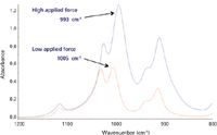
Figure 4: Band shift in kaolin at different applied forces.
The effective pathlength in ATR differs significantly for s- and p-polarization of the incident radiation, being higher for radiation polarized parallel to the plane of incidence. This enhances the absorbance of vibrations with a dipole change in the plane of incidence relative to those with a dipole change parallel to the plane (Figure 5). The two spectra in Figure 6 are from a cup made of polylactic acid, the difference being only that the sample was rotated through 90° between the two measurements. These differences are large enough to cause problems in identifying materials. Using a correlation algorithm that is commonly employed to check identity, the correlation between these two spectra gives a value of 0.903 — a typical threshold for identity checking would be 0.985.

Figure 5: Polarization in the ATR experiment.
A second example is seen Figure 7. This shows spectra of the polypropylene coating on a magazine cover when the sample is rotated through 90°. The relative intensity changes seen in bands between 1200 and 900 cm-1 are similar to those seen in transmission spectra of drawn polypropylene films using polarized radiation.
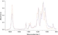
Figure 6: Spectra of a polylactic acid cup at different orientations.
Polarization effects may be seen even when the orientation of the sample on the surface is apparently random. This is because crystalline powders may adopt preferred orientations relative to the interface. The evanescent electric field has components both parallel to and normal to the interface. With a polarizer set perpendicular to the plane of incidence the evanescent field is parallel to the surface and has no component normal to the surface. The intensity of vibrations with dipole changes normal to the surface will be reduced. An example is provided by the spectra of kaolin when used to provide a smooth surface on paper. This sample has plate-like crystals that tend to orient themselves parallel to the surface. Some vibrations have dipole moment changes aligned largely in the plane of the crystals with others perpendicular. Setting the polarizer perpendicular to the plane of incidence greatly reduces the intensities of OH bands at 3694 and 3653 cm-1 while bands at 3670 and 3620 cm-1 are only changed a little (Figure 8). Similar variations in the relative intensities of different bands can be seen in the spectra of other compounds such as the α-polymorph of the anti-inflammatory drug indomethacin, even though the bulk material is not anisotropic (Figure 9). This is significant because differences in relative band intensities might be misinterpreted as indicating polymorphism, when they are a result of crystal morphology.
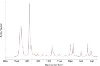
Figure 7: Spectra of polypropylene-coated paper at different orientations.
Problems with Inhomogeneous Materials
Suspensions and emulsions are problematic materials for ATR measurements. The issues stem from the fact that ATR only measures a shallow surface layer. Even for an apparently uniform material, like chocolate, the composition of the surface may differ considerably from that of the bulk. A second problem is that even though a suspension is stable, a surface layer may take some time to stabilize after it is freshly formed. Taken together these make quantitative measurements on such materials by ATR generally unsatisfactory. This is evident from comparing spectra of a commercial milk chocolate measured both by ATR and in transmission. Both spectra are dominated by features from lipids and sucrose (Figure 10). There are lipid contributions from CH2 chains at 2900 cm-1 and C=O groups at 1730 cm-1, and major features from sucrose appear above 3000 cm-1 (OH) and around 1000 cm-1. The differences are in part caused by the wavelength dependence of the effective pathlength in ATR. However, this is insignificant when comparing the intensities of the sucrose OH bands around 3300 cm-1 with the lipid CH2 bands at 2900 cm-1. It is clear that in the transmission spectrum the ratio of sucrose to lipids appears much higher than in the spectrum measured by ATR. This shows that the lipid concentration is much higher at the surface than in the bulk.
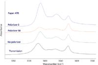
Figure 8: Spectra of kaolin-coated paper by polarized ATR and of kaolin by transmission in a KBr pellet.
Similar issues occur in measuring spectra of a hazelnut spread. The composition is rather similar to that of chocolate, but the material contains suspended solids in a highly viscous liquid matrix. ATR spectra measured with zinc selenide (ZnSe) and germanium (Ge) crystals have different depths of penetration because of their refractive indices. For a 45° angle of incidence, the penetration depth of ZnSe (refractive index 2.4) is about three times greater than that of Ge (refractive index 4.0). The spectrum obtained with ZnSe shows a considerably higher ratio of sucrose to lipid than that measured with Ge (Figure 11). Even though this result indicates that the sucrose concentration is lower at the surface than at greater depths, ATR has been of very limited use for depth profiling.
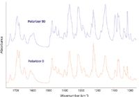
Figure 9: Spectra of α-indomethacin with different polarizations. Resolution 2 cm-1.
This suspension appears stable and does not separate on prolonged storage. However, this is not true for the shallow surface layer seen by ATR. Principal component analysis (PCA) of spectra recorded over a period of 15 min show that the intensity of the sucrose bands is increasing throughout this time (Figure 12).
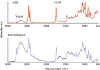
Figure 10: Spectra of milk chocolate by transmission and ATR.
Experimental
Spectra were recorded with a Perkin-Elmer (Seer Green, United Kingdom) Frontier FT-IR spectrometer at 4 cm-1 using a PerkinElmer single-bounce ATR accessory with a diamond element, except where indicated otherwise. The accessory provides a continuous readout of the applied force. Polarized spectra were measured using a Pike Miracle ATR Accessory (Pike Technologies, Madison, Wisconsin) with a ZnSe crystal. Samples were commercial materials. α-Indomethacin was prepared by the method of Kaneniwa and colleagues (3). All spectra are shown without correction for the wavelength dependence of the effective pathlength.
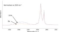
Figure 11: Spectra of a hazelnut spread with ZnSe and Ge crystals.
Summary
The convenience of ATR justifies its position as the preferred sampling method for most routine mid-IR measurements. However, ATR spectra suffer from sources of variation that are absent in simple transmission measurements. Relative band intensities are affected by changes in the applied force and also may be affected by sample orientation. Although such changes are obviously important for quantitative measurements, they can also affect qualitative identification which is a major use of ATR. Measurements of emulsions and suspensions are generally unsatisfactory as they are likely to be unrepresentative of the bulk material and also may change with time.

Figure 12: PCA of spread spectra over time.
References
(1) F.M. Mirabella, Internal Reflection Spectroscopy (Marcel Dekker, New York, 1993).
(2) F. Friedrich and P.G. Weidler, App. Spectry. 64(5) 500–506 (2010).
(3) N. Kaneniwa, M. Otsuka, and T. Hayashi, Chem. Pharm. Bull. 33(8), 3447–3455 (1985).
Richard Spragg is an applications scientist with PerkinElmer ASLS in Seer Green, United Kingdom. Direct correspondence to: richard.spragg@perkinelmer.com.
The Future of Neurodegenerative Disease Research and the Role of IR Imaging
May 21st 2025In the final part of this three-part interview, Ayanjeet Ghosh of the University of Alabama and Rohit Bhargava of the University of Illinois Urbana-Champaign talk about the key performance metrics they used to evaluate their model, and what the future of neurodegenerative disease research looks like.
Describing Their Two-Step Neural Model: An Interview with Ayanjeet Ghosh and Rohit Bhargava
May 20th 2025In the second part of this three-part interview, Ayanjeet Ghosh of the University of Alabama and Rohit Bhargava of the University of Illinois Urbana-Champaign discuss how machine learning (ML) is used in data analysis and go into more detail about the model they developed in their study.
AI and Infrared Light Team Up to Advance Soil Carbon Monitoring
May 19th 2025A team of international researchers has developed a faster, more accurate method to analyze soil carbon fractions using mid-infrared spectroscopy and deep learning. Their approach preserves the chemical balance of soil organic carbon components, paving the way for improved climate models and sustainable land management.

.png&w=3840&q=75)

.png&w=3840&q=75)


.png&w=3840&q=75)


.png&w=3840&q=75)


