Terahertz Pulsed Imaging for Nondestructive Testing of Pharmaceutical Products
In this column, Guest Columnist Philip Taday explores the use of terahertz spectroscopy for tablet coating analysis.

Tablet coatings are of great importance to both consumers and pharmaceutical manufacturers. By controlling the release of the active pharmaceutical ingredient, tablet coatings ensure bioavailability and minimize harmful effects and the waste of the drug by delivering it at the specific site and at the optimum level. These functions can be compromised if a coating is nonuniform or has defects.
The exceptional properties of terahertz radiation — including its low photon nonionizing energies and its ability to penetrate most nonpolar materials that can be opaque for visible light or low contrast for X-rays — make this radiation a very attractive tool for helping to understand pharmaceutical materials and products.
Until recently, the analysis of coating thickness relied upon indirect techniques, and it usually was determined by the weight gain of the coated tablet compared to the uncoated tablet core. Near-infrared (NIR) and Raman spectroscopic and imaging techniques that have been developed in recent years to yield information about the quality and integrity of the coatings usually are restricted to the outer surface of the tablet. To test the coating for uniformity or to analyze buried structures or even multiple layers within the tablet, the tablet must be cut and spectroscopic images must be acquired for each layer. However, in contrast to the NIR and mid-IR regions of the electromagnetic spectrum, many of the excipients used for coating solid dosage forms are transparent or semitransparent to terahertz radiation. Moreover, terahertz radiation can easily penetrate commonly used coating polymers. This in turn means that, unlike the aforementioned techniques, terahertz pulsed imaging (TPI) nondestructively provides spatially resolved information from below the surface of the sample (tablet). A nondestructive alternative for characterizing only the density variations within the tablet, and therefore only physical properties of a sample, is X-ray microtomography. However, long acquisition times, computational requirements, and the possibility of radiation-induced strain in the sample are limitations of this technique. Consequently, terahertz measurements are arguably more suited than any of the aforementioned techniques to monitor key quality attributes of the pharmaceutical solid dosage forms during manufacturing.
The 3D TPI measurements discussed in this column were performed using a TPI imaga 2000 system (TeraView, Cambridge, UK).
The method employed to generate terahertz pulsed radiation is based upon illuminating a biased photoconductive switch (antenna) by a femtosecond laser pulse with a photon energy greater than the bandgap of a gallium arsenide substrate. This process will lead to production of photocarriers — electrons and holes in the conduction and valence bands, respectively. Fast varying density of the photocarriers and their acceleration in the external field of the applied bias will generate an electromagnetic field radiating into free space in the terahertz frequency range. The nature of terahertz pulse is broadband (typically 0.06–3 THz, corresponding to 2–100 cm-1 ).
The detection of the incident terahertz pulse is also based upon a photoconductive antenna. Assuming that an above-band gap optical gating pulse is focused onto a photoconductive antenna-based detector, it will produce photocarriers in the antenna substrate. An incoming terahertz beam will induce a transient bias voltage across the antenna gap between the electrodes. If the incident terahertz electric field and induced photocarriers are both present, the photocurrent will flow across the gap. This current is proportional to the terahertz electric field. By varying the optical path length between terahertz and optical pulses, the entire terahertz time-domain signal can be sampled with both the amplitude and phase of the terahertz pulse available. This is in contrast to most spectroscopic techniques that yield only the signal intensity.
The components of the TPI system are shown in Figure 1. A Ti:sapphire laser provides a train of laser pulses that are split into a pump beam for terahertz generation and a probe beam for detection, both based upon photo-excitation of a gallium arsenide antenna. These two optical pulses are launched into separate optical fibers that link the TPI core unit with the tablet scanning unit. After leaving the output from the optical fibers in the tablet scanning unit, the pump and probe beams are focused onto the gaps of the photoconductive emitter and detector, respectively, using a silicon lens. A modulated bias was applied across the emitter electrodes and the detector gated output signal was fed to a lock-in amplifier. Reference for the lock-in is provided by the electric modulation of the emitter. A dynamic range of greater than 70 dB was demonstrated using time-gated and lock-in detection. To record the time evolution of the terahertz electric field, a rapid scan delay line is incorporated in the probe beam that systematically varies the delay between probe and pump beam at the detector. The generated terahertz signal from the emitter is focused by a silicon lens to a diffraction-limited spot on the tablet surface. The terahertz radiation reflected from the tablet is collected by the same silicon lens and focused onto the detector.
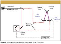
Figure 1
Prior knowledge of the tablet shape profile allows a six-axis robot arm to position the solid dosage form under investigation in focus and always normal to the incident terahertz beam. In this manner, a 3D terahertz image of the solid dosage form is acquired. When the terahertz pulse is applied on a tablet, part of the incident terahertz pulse is reflected from the tablet's outer surface. The other portion passes into the tablet and is partially reflected every time it encounters a new subsurface within the tablet, characterized by a different index of refraction. The resulting terahertz waveform thus consists of multiple pulses arriving at the detector at delayed times, depending upon the index of refraction and the thickness of the traversed layer.
Tablet Coating Analysis Key Metrics
3D TPI analysis of tablets identified the following key metrics (Figure 2) that could possibly be used to assess the variations in the individual batch average dissolution behavior of tablets produced using different weight gains or by changing some of the coating process parameters.
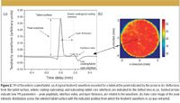
Figure 2
Terahertz electric field strength of the reflection peak from air–enteric coating interface depends on the outer coating refractive index value. The peak amplitude can be affected by the density of the coating of the surface.
Coating thickness is determined as the ratio of the peak position difference between the surface reflection and the interface reflection, divided by the refractive index value of the tablet coating. The coating thickness maps were created by plotting the coating thickness at each point of the tablet surface. They show the distribution and uniformity of the coating layer over the tablet surface and can be used to identify inhomogeneities or defects in individual tablet coatings.
The interface index is defined as the peak height ratio of the interface reflection and the surface reflection. The interface index gives a measure of the strength of reflection from buried surface and can give an indication of a change in physical composition at the interface.
As previously mentioned, the resulting terahertz waveform consists of multiple pulses (reflections) arriving at the detector at delayed times. These times depend upon the index of refraction and the thickness of the traversed layers.
The positive reflection peak at 0.00 mm time delay arises due to the reflection of the terahertz pulse from the tablet surface (that is, the air–enteric coating interface).
The positive reflection peak at approximately 0.15 mm originates from the enteric coating–subcoating interface — this moves to longer times as the weight gain of the applied enteric coating increases.
The negative reflection peak at approximately 0.20 mm results from the subcoating–tablet core interface — this moves to longer times with the enteric coating weight gain increase.
Formation of either positive or negative reflection peak corresponds to either positive or negative change that refractive index undergoes between the adjacent layers.
Data Analysis
The illustration of the formation of different terahertz reflections is shown in Figure 3. Each time the terahertz pulse encounters a new interface (that is, a physical–chemical change within the solid dosage form) that is associated with a change in the refractive index, it is reflected back to the detector. Because of the high signal-to-noise ratio of the terahertz technique, it is possible to detect very small changes in the refractive index and therefore detect various interfaces within the solid dosage form.

Figure 3
When the photoconductive antenna is illuminated with a laser pulse, it generates a train of pulses with decreasing amplitudes. These pulses (echo signals) arise due to the additional reflections from the antenna–air and detector–air interfaces. As the terahertz pulse propagates through the sample, it becomes modified by the sample response as well as the echoes. As a consequence, the resultant terahertz signal reflected from the sample is the convolution of the system response (terahertz signal emitted from the biased photoconductive antenna with contribution of any echo signals arising from the instrument itself — reflections from the photoconductive antenna and the detector) and the sample response to this signal. Depending upon the thickness of the semiconductor devices and the sample material, the unwanted additional signals can overlap with the main terahertz pulses, which further complicate the signal interpretation. To recover only the sample response and calculate the key metrics, the resultant terahertz waveform (raw data) is deconvolved with the system response by dividing the raw terahertz waveform, in frequency domain, with the reference waveform recorded with a metallic mirror. The deconvolution process is performed in such a way that high-frequency noise is suppressed by applying a numerical bandpass filter with a specified cutoff frequency. This procedure provides an axial resolution of approximately 38 μm. The actual value will depend upon the sample refractive index. Deconvolved data can be processed further to calculate coating thickness values at each pixel of the sample surface as well as the interface index values.
Detecting Process-Induced Changes
To give an example, enteric-coated tablets were analyzed using terahertz pulsed imaging. For two observed coating layers, the time-of-flight calculation was employed to calculate the thickness of each layer.
The deconvolved terahertz time-domain waveforms (Figure 4) carry information about physicochemical properties of coatings and layers within two different tablets of different weight gains.
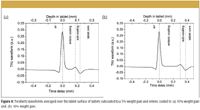
Figure 4
The formation of the positive reflection peak at around 0.20 mm (Figure 4) is indicative of the positive change in the refractive index at the transition from the enteric to the subcoating. This position varies with the increase of the weight gain of the applied enteric coating layer.
To highlight the existence of the additional features within tablets, Figure 5 shows a cross-sectional map of a 10% tablet (Figures 5a and 5b) and tablets from the batch that exhibit the internal structure at 10% (Figures 5c and 5d) and 16% (Figures 5e and 5f) weight gain. These tablets were from the same coating run taken from the coating pan at different times. The importance here is to understand whether this internal structure affects the performance of the drug release.
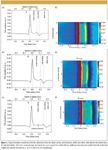
Figure 5
The image in Figure 6 clearly shows the effect of the fast coat on the enteric coating–subcoating interface in terms of uneven surfaces and discontinuity across the length. In some areas of the tablet the subcoating was "washed off" the tablet surface.
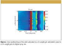
Figure 6
TPI Key Metrics
The time delay between the two reflection peaks, either reflection peaks between the outer tablet surface and the interface between the enteric and subcoating or between the enteric–subcoating interface and subcoating–tablet core, was used to calculate the thickness of either the enteric or the subcoating for every recorded pixel (Figure 7).
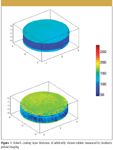
Figure 7
The terahertz images as well as the statistical analysis (Table I) reveal that the mean coating thickness (averaged over all three tablet surfaces) increases as the weight gain of the enteric coating increases.

Table I: Results from the statistical analysis
3D TPI reveals a change in the interface between the enteric and subcoating as the process conditions change (that is, coating viscosity and spray rate). This difference in the interface potentially indicates a change in adhesion between the two coating layers.
Key Metrics and Dissolution Behavior
As seen in Figure 8, a significant correlation exists between the nondestructive 3D TPI determined coating thickness and mean dissolution time determined for each individual tablet. Thus, 3D TPI reveals the positive correlation between mean dissolution time and the mean enteric coating thickness (averaged over all three tablet surfaces).
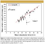
Figure 8
As observed in Figure 8, the tablet identified as Tablet 7 is an obvious outlier. The observed behavior might be explained by the following: Tablet 7 shows the thinnest subcoating. Elements of the additional structure within the enteric coating are less evident for this particular tablet.
Conclusion
TPI can be used to determine the coating thicknesses of pharmaceutical products. The thickness can then be correlated to not only the mean dissolution time but also to the onset of dissolution, which can be important in enteric-coated products. Weight gain, traditionally used as a nondestructive indicator of product performance, failed to provide enough information about the performance of the analyzed tablets. However, terahertz coating thickness could be correlated with the actual product performance.
This investigation has highlighted the potential of TPI to be used as a method for investigating tablet coating uniformity and integrity and coating–coating interface variations to establish process or formulation changes. Because TPI can be applied to tablets relatively quickly and nondestructively, it has the potential to be used as an online tool to aid understanding of the changes that could occur during development and manufacturing, and therefore ensure optimal performance of the finished pharmaceutical product.
Philip Taday is with TeraView Limited, Cambridge, U.K.

LIBS System Built on Microjoule High PRF Laser Identifies Aluminum Alloys for Recycling Potential
January 2nd 2024Differing grades of aluminum alloys have large differences in their composition, especially when it comes to trace elements, emphasizing the need for them to be evaluated for means of production, use, and recycling.