ICP-MS: Essential Steps to Optimize Matrix Tolerance
Special Issues
Inductively coupled plasma–mass spectrometry (ICP-MS) has good elemental coverage, low detection limits, and wide dynamic range, making it the technique of choice in many inorganic analytical laboratories. However, many sample types contain high levels of dissolved solids, which may be problematic for routine analysis using ICP-MS. Also, many new users focus on maximizing sensitivity when they optimize their systems, which can lead to degraded matrix tolerance. In this tutorial, we discuss the factors that affect the matrix tolerance of an ICP-MS instrument, and recommend steps that can be taken to optimize the key parameters.
Control the Level of Dissolved Solids
The maximum level of total dissolved solids (TDS) in samples to be analyzed using ICP-MS has long been accepted as 0.2%, or 2000 ppm. Above this level, drift is accelerated due to matrix deposits on the interface, analyte signals are reduced due to ionization suppression, and sensitivity is lower due to space charge effects during ion extraction and focusing.
An example of a typical sample dilution approach might involve a soil sample prepared using 0.2 g of dried material, digested, and diluted to a final volume of 100 mL (0.2 g/100 mL = 0.2% TDS). Note that the TDS limit is usually based on the inorganic dissolved solids, since the organic content will usually be decomposed during the sample preparation. Samples or digests that contain higher than 0.2% TDS would typically be diluted to reach this level.
As an alternative to liquid dilution, most modern ICP-MS instruments offer a facility to apply "aerosol dilution." Aerosol dilution uses an additional argon gas flow to dilute the aerosol after it emerges from the spray chamber. Together with a reduction in the nebulizer gas flow rate to reduce the amount of aerosol generated, this has the effect of diluting both the total amount of sample matrix passed to the plasma and the amount of water vapor present in the gas stream.
Aerosol dilution is much simpler and more cost effective than an automated liquid dilution system, which typically includes multiple pumps and switching valves, all linked using tubing and connectors that can clog or leak. Aerosol dilution also offers the following benefits compared to liquid dilution:
- Avoids errors and contamination. Aerosol dilution uses argon gas, rather than a liquid, as the diluent. This eliminates the possibility of adding contaminants in the diluent, and avoids dilution errors.
- Decreases interferences. The reduction in the amount of water vapor passed to the plasma means that the plasma does not expend as much energy on drying the aerosol, so the effective temperature is higher. Together with the lower level of oxygen from the reduced amount of water vapor, this leads to a reduction in the level of oxides and other polyatomic interferences.
- Reduces maintenance and improves stability. The lower aerosol density entering the plasma reduces the localized cooling around each droplet, so the droplets are dried and decomposed more efficiently. This improved decomposition reduces the amount of undissociated matrix that reaches the interface, so interface cleaning is less frequent and less drift occurs.
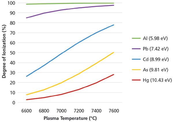
- Improves ionization of poorly ionized elements. Compared to the sensitivity obtained in a sample diluted using conventional liquid dilution, the higher temperature of the drier plasma under aerosol dilution conditions increases in the degree of ionization, particularly for poorly ionized analytes. Some of these analytes (beryllium, arsenic, selenium, cadmium, and mercury) are critical trace elements with low detection limit requirements. The effect of plasma temperature on the ionizationÂ-and therefore sensitivityÂ-of poorly ionized elements is illustrated in Figure 1.

Figure 1: Approximate degree of ionization (%) for several elements at different plasma temperatures. Illustrates how changes in plasma temperature have a greater impact on sensitivity for poorly ionized elements. First ionization potential shown (eV).
Select Appropriate Sample Introduction System and Settings
As a rule, sample introduction hardware and operating conditions that increase sensitivity will reduce matrix tolerance. Optimizing for maximum sensitivity can therefore lead to operating conditions that do not provide sufficient robustness for routine analysis of many sample types. Sample introduction options and settings that affect matrix tolerance include:
- Nebulizer type and sample flow rate. A low-flow nebulizer operating at 200 µL/min solution flow rate gives lower sensitivity, but better matrix tolerance, compared to a nebulizer operating at 1 mL/min. If samples contain particulates, an alternative nebulizer type, such as a v-groove or parallel path, is preferred.
- Spray chamber design and operating conditions. The spray chamber filters the primary aerosol, removing the larger droplets that would not be fully decomposed in the plasma. A double-pass or baffled spray chamber provides better filtering of the aerosol, so the droplet sizes are smaller and more uniform, improving matrix tolerance. Alternative spray chamber designs or gas flow settings may allow larger droplet sizes to pass through, which increases sensitivity, but leads to poorer matrix tolerance. Regardless of the design, cooling the walls of the spray chamber is recommended, as this condenses excess water vapor. Reducing the water vapor loading helps to maintain a higher plasma temperature.
- Plasma torch injector internal diameter. A wider diameter injector reduces the density of the aerosol in the plasma, and therefore improves the plasma's capacity to dry the aerosol droplets and decompose the sample matrix.
- Aerosol dilution. The lower matrix/vapor loading and higher plasma temperature provided by aerosol dilution improve matrix tolerance, allowing more variable, higher matrix samples to be measured accurately against simple aqueous calibrations.
Reduce Interferences and Maximize Plasma Robustness by Optimizing Plasma Conditions for Lower Cerium Oxide Ratio Formation (CeO/Ce)
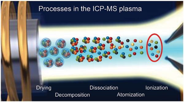
Having addressed the sample preparation and nebulizer/spray chamber/torch configuration, the plasma conditions should be optimized to maximize robustness. Plasma parameters are interrelated, with the different settings interacting to produce a trade-off between sensitivity and robustness. Plasma robustness is typically monitored using the cerium oxide (CeO/Ce) ratio. Cerium oxide is used as it is among the most strongly-bound metal-oxide ions, so a low CeO/Ce ratio indicates that the plasma has enough energy to dry the aerosol droplets, decompose the matrix, dissociate molecular species, and ionize the analyte atoms. These processes are illustrated schematically in Figure 2. Parameters that can be used to optimize the matrix tolerance of the ICP-MS plasma are:
- Carrier gas flow rate. A lower central channel gas flow rate reduces cooling at the back of the plasma, so the aerosol enters the hottest part of the plasma sooner, allowing more time for sample decomposition. For a given carrier gas flow, a wider torch injector also effectively increases the time the aerosol droplets spend in the hottest part of the plasma.
- Sampling depth. Increasing the distance between the load coil (plasma) and interface sampling cone allows more time for matrix decomposition and analyte ionization.
- Plasma radiofrequency (RF) power. Higher RF power means higher plasma temperature, and therefore better matrix decomposition. The temperature of the plasma central channel (where the aerosol droplets are) is also affected by the RF frequency. Lower RF frequency (27 MHz used on most ICP-MS systems) gives a higher central channel temperature than higher RF frequency (40 MHz as commonly used for inductively coupled plasma–optical emission spectrometry (ICP-OES).

Figure 2: Schematic illustration of the processes in the ICP-MS plasma, from aerosol droplet drying to analyte ionization.
Verify that the Selected Configuration and Settings Allow the Required Method Detection Limits (DLs) to Be Achieved for Critical Trace Elements
Optimizing the hardware configuration and operating parameters for robustness leads to reduced sensitivity. Consequently, the underlying detection limit performance must be checked under the selected robust method conditions.
Modern ICP-MS systems are capable of extremely high sensitivity when optimized for sensitivity rather than matrix tolerance. Optimizing for matrix tolerance as described above will reduce this sensitivity but should still allow the method requirements to be met. This needs to be confirmed using performance tests such as low level spike recoveries and assessment of method detection limit, as appropriate for the application.
Confirm Chosen Settings Allow High-level Analytes and Major Elements to Be Measured
An important consideration for multielement analysis is the capability of the ICP-MS to measure the major elements together with the trace analytes. For many commercial laboratories, this is a key requirement for maximizing productivity by allowing all the required elements to be determined in a single measurement. For this to be achieved routinely, the dynamic range of the ICP-MS detector must be as wide as possible.
Modern ICP-MS systems use a detector with a dynamic range of up to about 10 or 11 orders of magnitude. This ensures that the highest concentration major elements can be measured without requiring customized settings to attenuate the most intense signals. User-defined signal attenuation is not easy to apply when the sample types being measured are of variable and unknown composition, and where the major elements are not known in advance.
Monitor Long-term Stability Using Periodic Check Standards or Internal Standard Signal Responses
Once the ICP-MS has been optimized for robustness, and detection limits and dynamic range have been confirmed, method performance should be verified by analyzing a representative batch of samples.
Most regulated methods will include analysis of periodic check standards or similar in-run quality control (QC) to check that the calibration remains valid, and the signal has not drifted out of control. A periodic check standard is useful to confirm the ongoing validity of the calibration, but a better indication of the true sensitivity during a sample sequence can be obtained from plotting the internal standard (ISTD) signals for each sample. The ISTD signals are not corrected, so indicate any changes in sensitivity of the instrument due to drift or suppression, for every solution run throughout the entire batch.
For ICP-MS analyses, ISTDs are usually added automatically using an online mixing T-connector. If several ISTD elements are added, the ISTD plot can also indicate any mass-dependency in the signal change as well as enabling contamination of an ISTD element in a sample to be identified.
Ed McCurdy is an ICP-MS Product Specialist for Agilent Technologies in Cheshire, United Kingdom. Direct correspondence to: ed_mccurdy@agilent.com

High-Speed Laser MS for Precise, Prep-Free Environmental Particle Tracking
April 21st 2025Scientists at Oak Ridge National Laboratory have demonstrated that a fast, laser-based mass spectrometry method—LA-ICP-TOF-MS—can accurately detect and identify airborne environmental particles, including toxic metal particles like ruthenium, without the need for complex sample preparation. The work offers a breakthrough in rapid, high-resolution analysis of environmental pollutants.
FT-IR Microscopy, Part 2: Mid-IR Sampling with DRIFTS, IRRAS, and ATR
February 14th 2025Fourier transform infrared (FT-IR) microscopy using reflection methods (diffuse reflection, reflection/reflection-absorption, or attenuated total reflectance) typically requires less sample preparation than transmission. However, optimal results will depend upon the sample and, in particular, the sample surface.