Applications of Infrared Multiple Angle Incidence Resolution Spectrometry
Special Issues
Multiple angle incidence resolution spectroscopy (MAIRS) has proven useful for characterization of the in-plane (IP) and out of plane (OP) vibrations of thin films on solid substrates. The MAIRS technique computes the IP and OP spectra by performing a regression analysis on a series of oblique-incidence transmission spectra collected over a range of angles of a single thin film sample mounted on a transparent substrate. MAIRS replaces the more traditional technique of the collection of a transmission spectrum of a thin film on a transparent substrate, followed by collection of a reflection absorption spectrum of the same film on a metallic substrate. Often times, preparation of the same thin film on different substrates with different chemical and physical properties can be problematic. This paper will discuss details of the electromagnetic theory of MAIRS, and demonstrate its use in producing the IP and OP spectra of several thin film samples.
Multiple angle incidence resolution spectrometry (MAIRS) has proven useful for characterization of thin films by revealing the in-plane (IP) and out of plane (OP) components of molecular vibrations in the film on a solid substrate. The MAIRS technique computes the IP and OP spectra by performing a regression analysis on a series of oblique-incidence transmission spectra collected over a range of angles of a single thin-film sample mounted on a transparent substrate. MAIRS replaces the more traditional technique of the collection of a transmission spectrum of a thin film on a transparent substrate, followed by collection of a reflection absorption (RA) spectrum of the same film on a metallic substrate. Often times, preparation of the same thin film on different substrates with different chemical and physical properties can be problematic. This article discusses details of the electromagnetic theory of MAIRS with respect to multivariate analysis. We describe an accessory and software that was developed exclusively for MAIRS and demonstrate its use in producing the IP and OP spectra of thin film samples.
Thin-film technology is highly dependent on understanding the structure of the film on a molecular level as it is deposited on a surface. The performance of a film in its desired application, whether in electronics, optics, or chemical sensors, is dependent on achieving a specific orientation of the chemical groups relative to the surface.
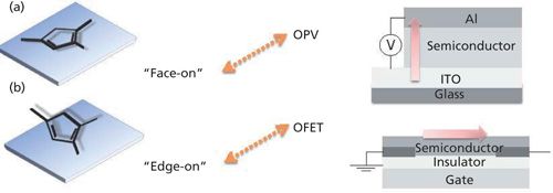
For example, poly(3-hexylthiophene) (P3HT) is a well-known p-type semiconductor polymer, and it can be used for applications as an organic photovoltaic (OPV), or as an organic field effect transistor (FET). P3HT must have a particular orientation on the surface, however, for use in these two types of devices. In an OPV, two electrodes sandwich the semiconductor layer, and the electric current flow is perpendicular to the electrode surface. Because the electric current runs across the molecular layers, the molecular plane must be parallel to the device surface, as shown in Figure 1a. This orientation is called face-on.
In an organic FET, on the other hand, the current flows parallel to the gate surface, as in Figure 1b, and the molecular axis of the thiophene rings must be perpendicular to the surface in the edge-on orientation. Therefore, the orientation of the thiophene ring on the surface must be controlled and accurately determined for each application.
The orientation of the thiophene rings of P3HT on the surface can be determined by X-ray diffraction (XRD), but XRD requires crystallinity of the film. High crystallinity is not always achievable, however, as the crystallinity can be influenced by the film deposition parameters, such as solvent, spin-coat speed, and tail length. P3BT, with a shorter alkyl tail, exhibits a diffraction peak in its XRD pattern (data not shown), from which a layer spacing can be determined, but P3HT does not, which indicates that P3HT is deposited on the surface with no ordering of the layers. Infrared (IR) spectroscopy, however, can still be used to examine the structure of the film on the surface irrespective of crystallinity, and chemical information of each functional group can be obtained.
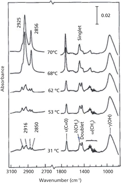
The potential of IR spectroscopy for thin-film analysis is briefly introduced here. IR spectra of a nine-molecular-layer (ML) Langmuir Blodgett (LB) film of stearic acid deposited on silver is shown in Figure 2 (1) as a function of temperature.
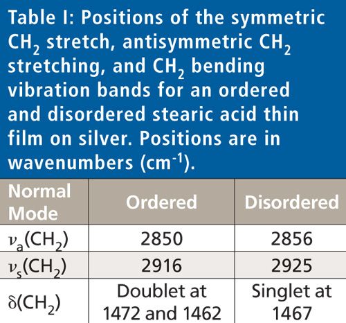
At ambient temperature, the symmetric and antisymmetric CH2 stretching vibration bands appear at 2850 and 2916 cm-1, indicating the film is highly ordered, as shown in Table I.
As the film is heated it becomes disordered, as evidenced by the peak shift of the CH2 stretching vibration bands to 2856 and 2925 cm-1, respectively. Changes in the CH2 bending vibration band are observed as well, from a doublet at 1472 and 1462 cm-1 for the ordered conformation, to a singlet peak at 1467 cm-1. Thus, IR spectroscopy can be used to not only obtain the spectra of disordered layers, but the peak positions can also be used to determine crystallinity.
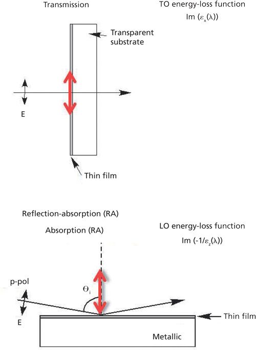
The determination of the molecular structure of thin films on surfaces required the collection of two spectra of the film: one in transmission on an IR transparent substrate and one in reflection on a metallic surface. This requirement has been dictated by an electromagnectic theory-that is, surface selection rules. For electromagnetic radiation incident to a film in transmission at the normal angle of incidence, the electric field oscillation is parallel to the surface, and only the surface-parallel component of the normal mode, the in-plane (IP) bands, are measured as presented in Figure 3. In the case of IR light incident to a film on a metal surface at grazing angles of incidence, the electric field oscillation at the metal surface is perpendicular to the surface, and only the surface-normal component of the normal modes, the out-of-plane (OP) bands, are detected.
With the combination of the IP and OP vibrational spectra, the orientation of the normal mode of a functional group relative to the surface normal can be calculated by equation 1 via the ratio of the measured intensities of the same mode of the two spectra.

To obtain both the IP and OP spectra of a thin film, it has been necessary to prepare the film on an IR-transparent substrate for transmission measurements, and on a metallic substrate for reflection-absorption measurements. In practice, however, preparation of an identical thin film on two substrates with different surface properties can be very difficult or impossible to achieve. Therefore, a technique that simultaneously generates the IP and OP spectra of a single thin film on one substrate is highly desirable.
Multiple Angle Incidence Resolution Spectrometry
Theory
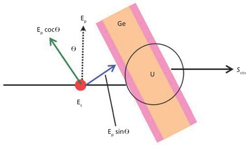
A detailed description of the multiple angle incidence resolution spectrometry (MAIRS) theory has been previously published (2), which is summarized here. With normal incident light in transmission, the infrared spectrum of a thin film only measures the IP component of the normal modes. However, as the oblique angle of incidence is increased, the spectrum contains an increasing component of the OP spectrum, as presented in Figure 4, where the recorded single-beam (light intensity) spectrum involves a linear combination of the IP and OP spectra (SIP and SOP, respectively), as described in equation 2.

The last term u is a collection of un-modeled reflection factors. For a series of spectra collected at different angles of incidence, a collection of equations like equation 2 can be written in a matrix form.
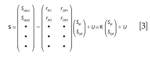
For measurements on high refractive-index substrates using unpolarized light, matrix R is

Equation 3 is a classical least squares (CLS) regression model, and the optimal solution is obtained as the least-squares solution. CLS works well in this case because the number of components can be rigorously fixed to only two, SIP and SOP (2).
pMAIRS
MAIRS using unpolarized light works well on a thin film deposited on a high-refractive-index substrate. The use of high-index substrates, such as germanium, limits the optical throughput because of high reflection losses and limits the spectral range. The MAIRS theory has been updated (3) to allow the use of p-polarized light and low index of refraction substrates, such as surface-oxidized silicon and CaF2. Since only the p-polarized component is used, the new technique is called pMAIRS. The only difference in the theory between MAIRS and pMAIRS is the expression of the R matrix, where the new matrix for pMAIRS, Rp, becomes:

pMAIRS enables the use of a wider selection of substrates and wavelength range, making it the preferred technique.
Experimental
MAIRS
A clean germanium (Ge) substrate was mounted in the sample holder of an automated MAIRS accessory (Thermo Fisher Scientific) and mounted in the sample compartment of a Thermo Scientific Nicolet iS 50 FTIR spectrometer configured with an MCT/A detector and controlled by OMNIC software (Thermo Fisher Scientific). The automated MAIRS accessory rotates the oblique angle of incidence of the infrared light on the Ge substrate with a motorized stage. The MAIRS accessory was controlled by MAIRS software (Thermo Fisher Scientific) in conjunction with spectral collection by OMNIC.
A series of eight single-beam background measurements was collected on the Ge substrate between 10° and 45° oblique angle of incidence, by coadding 2000 scans at 4 cm-1 resolution at each angle. A five-molecular-layer Langmuir-Blodgett (LB) film of cadmium stearate (CdSt) on the Ge substrate was prepared by using an LB trough, and a series of single-beam spectra of the LB film was collected as described above. When the sample and background data collection were completed, the IP and OP spectra of the CdSt film were automatically computed using equations 3 and 4 by MAIRS software.
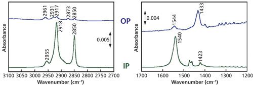
The IP and OP spectra of the CdSt LB film are shown in Figure 5. These spectra perfectly correspond to the conventional transmission and RA spectra collected separately (2).
pMAIRS
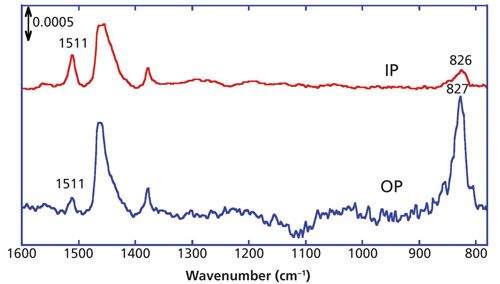
A spin-coated film of P3HT on a silicon (Si) substrate was prepared and analyzed using the MAIRS accessory with a polarizer set to p-polarization. The IP and OP spectra of the P3HT film were computed with pMAIRS software (Thermo Fisher Scientific) using equations 3 and 5, and are presented in Figure 6 (3).
Results and Discussion
P3HT is a polythiophene with a hexyl chain as a tail. When the tail is a little shorter, such as a butyl group in P3BT, the spin-coated film exhibits crystallinity, while the spin-coated P3HT exhibits minimal crystallinity. XRD can give no insight into the structure of P3HT on Si, but we can still discuss the molecular structure in the film using the IR pMAIRS spectra.
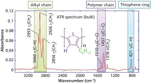
The key IR bands of interest of P3HT are shown in Figure 7 for a bulk sample collected by the ATR technique. The bands in the C-H stretching vibration region respond to the molecular conformation by band location. These bands are useful to discuss the orientation of the hydrocarbon tail. The C=C stretching vibration bands near 1500 cm-1 respond to the conjugation length along the polymer chain, and they are also useful to discuss the orientation of the long axis of the thiophene ring. The band at 820 cm-1 is the out-of-skeleton C-H bending mode on the thiophene ring, which can be used to determine the molecular orientation of the z-axis of the thiophene ring. Please note that this information is available from the infrared spectrum irrespective of crystallinity.
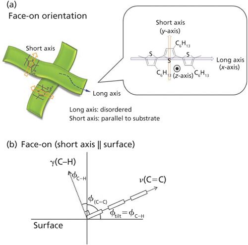
The most significant band in the OP spectrum of P3HT (Figure 6) is the C-H out-of-plane bending mode at 827 cm-1, while the same band is suppressed in the IP spectrum. This straightforwardly indicates that the z-axis of the thiophene ring is oriented perpendicular to the surface, with the tilt angle of this vibration computed to be 28° from surface normal via equation 1. In a similar manner, the long axis of the thiophene ring is computed to be 63° from surface normal, using the IP and OP intensities of the C=C stretching vibration band. As found in the diagram in Figure 8b, when the short axis of the thiophene ring is parallel to the surface, the summation of angles of the C-H out-of-plane bending and the C=C stretching vibration modes is theoretically expected to be 90°, which in this case is experimentally determined to be 91°.
From the combination of the analysis of the infrared spectra, which provides insight into the orientation of different functional groups in the thin film, and the XRD pattern, which shows a lack of crystallinity in the film, we have obtained a picture that the short axis of the thiophene ring is parallel to the surface, whereas the long axis is nearly disordered.
Conclusions
IR MAIRS and pMAIRS provide a powerful new tool to the surface scientist to determine the molecular structure and orientation in a thin film on an IR transparent substrate. The MAIRS techniques replace a tedious, and sometimes impossible, combination of sample preparation and analysis of identical films on both transparent and reflective substrates. The process of MAIRS data collection and processing has been automated with a motorized accessory installed in a Fourier transform (FT)-IR system under control of software that collects the IR spectra and performs chemometric analysis to produce the IP and OP spectra of a single film thin on one substrate.
References
(1) J. Umemura, S. Takeda, T. Hasegawa, and T. Takenaka, J. Mol. Struct.297, 57–62 (1993).
(2) T. Hasegawa, J. Phys. Chem. B106, 4112–4115 (2002).
(3) N. Shioya, T. Shimoaka, K. Eda, and T. Hasegawa, Phys. Chem. Chem. Phys. 17, 13472–13479 (2015).
David Drapcho is with Thermo Fisher Scientific in Madison, Wisconsin.
Takeshi Hasegawa is with the Institute for Chemical Research at Kyoto University in Gokasho Uji-city, Kyoto, Japan.
Direct correspondence to: david.drapcho@thermofisher.com
Accurate Plastic Blend Analysis Using Mid-Infrared Spectroscopy
May 15th 2025Researchers at the Sinopec Research Institute have developed a novel method using virtually generated mid-infrared spectra to accurately quantify plastic blends, offering a faster, scalable solution for recycling and environmental monitoring.
How Spectroscopy and Science are Reshaping Gemology
May 13th 2025A historical and technical overview from the Gemological Institute of America (GIA) explores how advanced scientific instruments—particularly spectroscopic methods—have transformed gem identification. From refractometers to modern spectrophotometers, this deep dive highlights the evolving challenges and solutions in gem testing.
How Infrared Light Reveals the Truth About Gemstones
May 12th 2025New research from the Gemological Institute of America highlights the essential role of infrared spectroscopy in identifying gemstones, detecting treatments, and distinguishing natural from synthetic gems. The technique’s precision and non-destructive nature have made it an indispensable tool in modern gemology.

.png&w=3840&q=75)

.png&w=3840&q=75)


.png&w=3840&q=75)


.png&w=3840&q=75)


