Overview of High-Efficiency Transmission Gratings for Molecular Spectroscopy
This article provides a basic overview of the capabilities of transmission gratings optimized for molecular spectroscopy.
This article provides a basic overview of the capabilities of transmission gratings optimized for molecular spectroscopy. These gratings offer near 100%, polarization-insensitive efficiency over a broad wavelength range and are ideal for applications such as Raman spectroscopy where the available light intensity from the sample is very low. The design, manufacturing, and performance of the two most commonly used types of transmission gratings — the surface relief transmission grating (SRTG) and the volume phase hologram (VPH) — are described and examples of the two grating types are discussed.
Most diode array–based diffractive spectrometers for the ultraviolet (UV), visible (vis), and near-infrared (NIR) spectral ranges use reflection-type diffraction gratings and are generally optimized for high resolution rather than high optical throughput. During the past 5–10 years, transmission-type gratings have been developed that provide near 100% efficiency for any polarization. These gratings have found widespread use for Raman spectroscopy and astronomy, where very little light is available, but elsewhere the awareness of the distinct benefits provided by transmission gratings seems quite limited. The purpose of this article is to provide a basic overview of the capabilities of transmission gratings optimized for molecular spectroscopy. Specifically, we will describe the two most commonly used types of gratings: the surface relief transmission grating (SRTG) and the volume phase hologram (VPH).
Transmission Grating Basics
This section describes the three key performance parameters of a transmission diffraction grating: the angular dispersion, the diffraction efficiency, and the bandwidth of the grating.
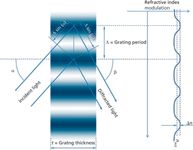
Figure 1: Transmission grating structure. Key grating parameters: Î = grating period; t = grating thickness; nAVE = average refractive index; and În = refractive index modulation.
Angular Dispersion: The Grating Equation
A transmission (or phase) grating consists of a region with a periodic modulation of the refractive index as shown in Figure 1. The period of the index modulation is on the same order of magnitude as the wavelength, and the form of the modulation can be sinusoidal, rectangular, triangular, or even more complex. From the plane wave ray tracing drawn on Figure 1 it can be seen that the plane waves add up in phase for exit angles β that fulfill the following criteria:

Equation 1 is the general grating equation that is valid for any grating structure. The term m is the order of diffraction, and in the remainder of this article we will consider first-order diffraction (m = 1) only.
For a certain spectrometer design, the center wavelength as well as the period Λ (or groove density G = 1/Λ) for the grating are often given parameters that cannot be freely chosen. Furthermore, a spectrometer is used in a range of wavelengths around the center wavelength and equation 1 determines the angular dispersion of this wavelength range.
Diffraction Efficiency
Although the grating equation determines the angular direction (β) of the diffracted light as a function of wavelength (λ), it does not say anything about the diffraction efficiency. The calculation of the diffraction efficiency for a transmission grating geometry generally requires complicated numerical methods such as rigorous coupled wave theory (1) for solving Maxwell's equations. However, Baldry and colleagues (2) approximated analytical equations based on Kogelnik's original work from 1969 (3) to provide a basic relationship between the physical parameters of the gratings and the diffraction efficiency and bandwidth of the grating. This analysis is based on a pure sinusoidal index modulation and is surprisingly accurate for a certain range of gratings. Based on this analysis, it can be shown that a grating's diffraction efficiency, for a fixed grating period and center wavelength, depends on three factors:
- the average refractive index (nAVE)
- the thickness of the grating (t)
- the index modulation (Δn)
Figure 2 illustrates the effect of the average refractive index. The figure shows the diffraction efficiency versus grating thickness for three different average indices and constant index modulation. First of all, the diffraction efficiency of both the transverse electric (TE) polarized and the transverse magnetic (TM) polarized wave oscillates between 0% and 100% efficiency with varying grating thickness. However, while the period of the oscillation of the TE diffraction efficiency is almost independent of the average index, the oscillation of the TM diffraction efficiency depends strongly on the average index. For certain values of the average refractive index (for example, 1.285 in Figure 2), the TE and TM can peak at the same grating thickness. This situation is naturally very desirable because it provides a polarization independent efficiency around the center wavelength.

Figure 2: Diffraction efficiency for TE and TM polarization versus grating thickness for three different average indices in the grating area. Fixed grating parameters: λc = 840 nm, Π= 566 nm, and α = β (Littrow configuration).
The effect of the refractive index modulation is illustrated in Figure 3 for the case of a polarization-sensitive design (average index = 1.200) and a polarization-insensitive design (average index = 1.285). From Figure 3 it can be seen that the oscillation frequency of the TE and TM waves increases with increasing index modulation but the relative peak position of TE and TM stays the same.
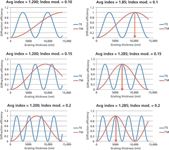
Figure 3: Diffraction efficiency versus grating thickness for average indices of 1.2 (left column) and 1.285 (right column) and for three different index modulation strengths. Fixed grating parameters: λc = 840 nm, Π= 566 nm, and α = β (Littrow configuration).
To summarize,
- The average refractive index controls whether polarization independent ~100% diffraction efficiency can be obtained.
- The index modulation controls the ideal thickness of the grating.
As will be demonstrated in the next section, such nearly 100% efficient, polarization-independent gratings can be produced as both SRTGs and VPHs. The high polarization-independent efficiency is what makes transmission gratings so powerful.
Bandwidth
So far, we have only considered the grating efficiency at a single wavelength. However, a spectrometer needs to analyze a range of wavelengths around the center wavelength. From the article by Baldry and colleagues (2) the full width at half maximum (FWHM) bandwidth of the grating can be calculated by

It has been assumed that the grating is used in the Littrow configuration where α = β. From equation 2 it can be seen that the bandwidth of the grating is inversely proportional to the grating thickness t.
Technologies
This section provides some insight into the manufacturing methods for SRTG and VPH gratings and presents some of the fine-tuning that can be done to design practical polarization-independent, high-efficiency gratings.
Surface Relief Transmission Gratings
SRTGs can be manufactured by etching into the surface of a glass substrate using a mask layer to define the periodic pattern. If fused silica is used as the substrate, gratings for wavelengths ranging from UV through NIR can be made. The index modulation goes from ~1.5 in glass to 1.0 in air — that is, an index modulation of ±0.25. The periodic pattern can be created by either a holographic technique or by using a conventional photo-mask. By controlling the pattern exposure and etching process the following parameters can be varied (within certain limits):
- The shape of the grating "teeth" — both sinusoidal and rectangular is possible
- The grating thickness, that is, the etching depth
- The duty cycle of the index modulation, that is, the width of the high index portion relative to the total period
- The sidewall angle of the grating structures — even asymmetric triangular (blazed) grating structures can be produced
Furthermore, dielectric materials with refractive indices different than the glass substrate can be added to the structure. Figure 4 shows the various parameters that can be used to optimize the grating's diffraction efficiency.
As discussed in the previous section, a high-efficiency, polarization-independent design requires that the average index, the index modulation, and the grating thickness are controlled and — for the SRTG — this is done by choosing the physical grating parameters appropriately. For instance, for a pure rectangular SiO2 grating profile the average index can be controlled between 1.0 (air) and ~1.5 (SiO2) by choosing the duty cycle appropriately. A 50% duty cycle would yield an average index of ~1.25 and an index modulation of ~0.25. By adding dielectric layers with an index larger than glass, the average index and index modulation can be made even larger than 1.5 and 0.25, respectively.
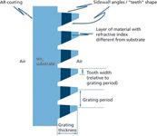
Figure 4: SRTG structural parameters.
When light propagates through the complete SRTG in Figure 4 it passes through three transitions coming from left to right: the air–glass interface; the glass–grating interface; and the grating–air interface. Special care must be taken in the grating design to avoid Fresnel reflections at these interfaces. The first air–glass interface simply requires an antireflection (AR) coating, but the glass-grating and grating-air interfaces must be designed such that the structure itself acts as AR transitions.
Volume Phase Holograms
VPHs are typically manufactured in a dichromated gelatin (DCG) that is sandwiched between two glass substrates as shown in Figure 5. The DCG is transparent from ~350 nm through NIR, so VPHs generally cannot be made for UV spectroscopy. The refractive index of DCG can be changed permanently by illumination with laser light. The permanent index modulation is created in the DCG by illuminating the material with an interference pattern (holographic technique). The thickness of the grating is simply the thickness of the DCG layer. The index modulation and average index can be controlled by the exposure intensity or exposure time of the illumination. Unexposed DCG has a refractive index of 1.54 and strongly exposed DCGs yield a minimum average index of ~1.25 and a maximum index modulation of ~0.15.
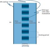
Figure 5: VPH grating structural parameters.
A benefit of the VPH type of gratings is that the grating structure is fully protected between two glass plates, which makes handling and cleaning less of an issue compared to SRTGs.
Similar to the SRTG, the glass–air interfaces in the VPH must be AR-coated. The VPH process does not provide a way of controlling the glass–grating interfaces.
Comparison of SRTG and VPH
With the parameter space available by the manufacturing techniques described above, both SRTGs and VPHs can provide high-efficiency, polarization-independent diffraction gratings. In general, SRTGs provide high index modulation (>0.25) and VPHs provide lower index modulation (<0.15). This means that VPHs typically require thick gratings (t > 5λ) and SRTGs require thinner gratings (t < 2λ).
The bandwidth of the grating is inversely proportional to the thickness of the grating, which means that SRTGs will provide a wider bandwidth than VPHs.
Table I provides a general overview of the two transmission grating types.

Table I: Comparison of SRTG and VPH capabilities
Grating Example
To illustrate how effective transmission gratings can be, we will consider two common spectrometer applications: a Raman spectrometer with a laser wavelength of 785 nm and a UV spectrometer.
High-Dispersion Raman grating for 785 nm
The first example is a high-dispersion grating well suited for Raman spectroscopy at a laser wavelength of 785 nm. The groove density of the grating is 1765 lines/mm (with a 566-nm period) and the angle of incidence in air is 50°. Ideally, the grating should provide polarization-independent high efficiency from 785 nm to 1000 nm. We used a finite element method (4) to solve Maxwell's equations combined with topological optimization (5) to find the best VPH and SRTG grating structures for this problem.
Figure 6 shows the resulting theoretical efficiencies for the SRTG and the VPH. The efficiencies are very high for both gratings and both polarizations at the center wavelength. As expected, the VPH displays a smaller bandwidth than the SRTG. Also plotted on Figure 6 are real measurements on realized SRTG and VPH gratings, which confirms that an efficiency of >90% can be obtained at the peak wavelength and >80% efficiency is obtained over a 200-nm bandwidth around the peak.
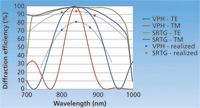
Figure 6: Diffraction efficiencies for SRTG and VPH gratings. The solid lines are theoretical curves and the colored squares are actual measurements on realized gratings.
UV Grating
The second example is a broadband UV grating for the 190–435 nm wavelength range. This grating has a groove density of 2420 lines/mm (period of 413 nm). Since this is a UV grating we have only considered a SRTG. Figure 7 shows the theoretical grating efficiency as well as the efficiency measured at three different wavelengths. The error bars indicate the total spread of efficiency over more than 60 individual gratings. As can be seen, the efficiency is high for both polarizatons and fairly flat across the complete range from 190 nm to 435 nm.
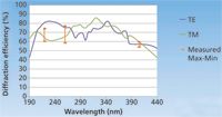
Figure 7: Diffraction efficiencies for an SRTG UV grating in pure fused silica. The solid lines are theoretical curves and the marks with error bars are actual measurements on realized gratings.
Summary
In summary, we have shown how near 100% efficiency, polarization-independent gratings can be designed by choosing the average refractive index, index modulation, and grating thickness appropriately. Furthermore, we have described two types of transmission gratings — the surface relief transmission grating (SRTG) and the volume phase hologram (VPH) — and shown that both types can provide the average index, index modulation, and grating thickness required for producing gratings with near 100% efficiency. VPHs generally have weak index modulation and SRTGs have strong index modulation. As a result, VPHs generally have thick gratings and a smaller bandwidth compared to SRTGs, which have thin gratings with a larger bandwidth. SRTGs based on fused silica can be made for any wavelength range from UV through NIR and VPH can be made for any range from ~350 nm through NIR.
References
(1) M.G. Moharam and T.K. Gaylord, J. Opt. Soc. Am.71, 811–818 (1981).
(2) K. Baldry et al., Publ. Astron. Soc. Pac.116, 403–414 (2004).
(3) H. Kogelnik, The Bell System Technical Journal48, 2909–2947 (1969).
(4) J. Jin, The Finite Element Method in Electromagnetics (Wiley, Hoboken, New Jersey, 2002).
(5) J. Jensen and O. Sigmund, Laser Photonics Rev.5, 308–321 (2011).
Thomas Rasmussen is VP Business Development for Sales and Marketing at Ibsen Photonics in Farum, Denmark. Direct correspondence to: Thomas.Rasmussen@ibsen.dk

NIR Spectroscopy Explored as Sustainable Approach to Detecting Bovine Mastitis
April 23rd 2025A new study published in Applied Food Research demonstrates that near-infrared spectroscopy (NIRS) can effectively detect subclinical bovine mastitis in milk, offering a fast, non-invasive method to guide targeted antibiotic treatment and support sustainable dairy practices.
Karl Norris: A Pioneer in Optical Measurements and Near-Infrared Spectroscopy, Part II
April 21st 2025In this two-part "Icons of Spectroscopy" column, executive editor Jerome Workman Jr. details how Karl H. Norris has impacted the analysis of food, agricultural products, and pharmaceuticals over six decades. His pioneering work in optical analysis methods including his development and refinement of near-infrared spectroscopy, has transformed analysis technology. In this Part II article of a two-part series, we summarize Norris’ foundational publications in NIR, his patents, achievements, and legacy.
AI-Powered SERS Spectroscopy Breakthrough Boosts Safety of Medicinal Food Products
April 16th 2025A new deep learning-enhanced spectroscopic platform—SERSome—developed by researchers in China and Finland, identifies medicinal and edible homologs (MEHs) with 98% accuracy. This innovation could revolutionize safety and quality control in the growing MEH market.