Spatial Resolution in IR Reflectance Imaging — NIR, Mid-IR, and ATR
Application Notebook
When images are measured in reflectance, the observed structure is not necessarily just that of the sample surface.
When images are measured in reflectance, the observed structure is not necessarily just that of the sample surface. The two-dimensional (2D) images produced by near-infrared (NIR) and mid-IR imaging are representations of three-dimensional (3D) objects. In reflectance images the effective spatial resolution is affected by how far the radiation penetrates into the sample as well as by diffraction and the pixel size. NIR images are typically dominated by diffuse reflection with the result that in practice spatial resolution is limited by the penetration depth. Mid-IR reflectance images may contain both specular and diffuse components. These have different spatial resolutions as the specular component shows purely surface structure. In attenuated total reflectance (ATR) images the resolution has a component that depends on the distribution of components within a surface layer corresponding to the penetration depth, which is proportional to wavelength. We illustrate these different contributions to the observed resolution with images of materials with known 2D and 3D structures.
What do we measure in reflection? For the majority of samples, transmission measurements are not possible so spectra have to be obtained by reflectance. This involves either external reflection, often divided into specular and diffuse reflection, or attenuated total reflection (ATR). What you see in external reflection is the sum of what is reflected from the surface (specular or Fresnel reflection) and what penetrates into the sample before emerging (diffuse reflection). You see only surface reflection from a continuous uniform material where radiation that penetrates is not scattered back to the surface. Very strongly absorbing materials also show only surface reflection as the radiation that penetrates is all absorbed. With scattering materials some radiation that penetrates the material returns to the surface by encountering interfaces where there is a change of refractive index. The relative amounts of surface and diffuse reflection depend on the absorptivity and particle sizes of the sample and are wavelength dependent. Small particle size and weak absorption increase the amount of diffuse reflection. In practice, diffuse reflection dominates in the near infrared (NIR) whereas spectra in the mid-IR often show significant contributions from both surface and diffuse reflection.
How does this affect spatial resolution? In an imaging experiment, separate spectra are measured for each pixel while the incident radiation covers the whole area. If reflection comes only from the surface, the spatial resolution should depend simply on diffraction and the pixel size. However, any radiation that penetrates a scattering sample takes a random path through the material and will not all return to the point at which it entered the sample. Thus, the radiation contributing to any pixel in the image is a combination of rays from some volume underneath the point on the surface that is being observed. The deeper the radiation can penetrate into the sample and return without being absorbed, the larger this volume will be. If we assume isotropic scattering, the average lateral displacement from the point of incidence to where the radiation emerges will be similar to the average depth to which the radiation penetrates. This will cause blurring of the image by an amount that depends on the average penetration depth. There have been several attempts to estimate the depth that the radiation penetrates (1,2). These suggest average values in the range of 50–100 µm for NIR observations of materials such as pharmaceutical tablets. As a result, the spatial resolution achieved in NIR reflection images is likely to be in this range. This is in contrast to what is observed with the metal-on-glass reflection targets normally used where diffraction limited spatial resolution is better at the shorter wavelengths of the NIR region than in the mid-IR.

Figure 1: Diffuse reflection and transmission.
Penetration Depth in Diffuse Reflection
One way to estimate the penetration depth is by comparing the band intensities in transmission and reflection for a scattering sample. The absorbance is proportional to the distance traveled inside the sample. In transmission, this distance is proportional to the thickness of the sample, but in reflection it is proportional to twice the average penetration depth (Figure 1). One sample used was an acetaminophen tablet ground down to a thickness of 1.1 mm. The ratio of the absorbances at 8800 cm-1 measured in transmission and reflection is 18:1. From this, the average penetration depth is calculated as 30 µm (Figure 2). Similar measurements on pressed pellets of other materials give average depths of 40 µm to 60 µm (Table I). Because these are average depths we can conclude that some rays must penetrate significantly further. This will produce blurring of 50–100 µm.
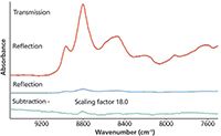
Figure 2: Spectra of an acetaminophen tablet.
Measuring Spatial Resolution in Scattering Materials
We prepared a sample by pressing a pellet of microcrystalline cellulose on top of a pressed pellet of polyethylene, giving a flat boundary between the two materials. Microtoming one edge of the pellet in a direction parallel to the interface gave a flat sample with the boundary perpendicular to the surface. Images were obtained with a PerkinElmer Spotlight system with a pixel size of 6.25 µm over the 6000–1400 cm-1 range (Figure 3). The spectra include dispersive features characteristic of Fresnel surface reflection such as the polyethylene CH2 absorptions around 2900 cm-1, strong absorptions such as the broad cellulose OH band at 3500 cm-1, and weak NIR absorptions.

Table I: Estimated NIR penetration depths
As expected, an image based on the polyethylene CH2 feature at 2864 cm-1 (Fresnel reflection) has a sharp boundary. In addition, it reveals an anomaly on the surface of the polyethylene layer at a distance of about 50 µm from the interface. An image of the strong cellulose OH absorption at 3600–3400 cm-1 shows a similar sharp boundary and indicates that the anomaly results from a flake of cellulose, something that is confirmed from the individual spectra. The sharp boundary illustrates how the strong absorption limits radiation that penetrates the sample returning to the surface. In contrast, the weak absorptions of the NIR region lead to much more diffuse images with features from one layer visible up to 100 µm away from the boundary. The polyethylene layer has significantly less scattering than the cellulose layer, which probably explains why the cellulose features appear to extend farther beyond the boundary.
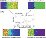
Figure 3: Images from a two-layer sample.
What Is the Penetration Depth in ATR Imaging?
The effective penetration depth is related to the wavelength λ, the refractive indices of crystal and sample n1 and n2, and the angle of incidence θ.
The effective penetration depth dp is given by

where λ is the wavelength, n1 is the refractive index of the crystal, θ is the angle of incidence, and n21 is the ratio of refractive indices of sample and crystal.
In the converging beam of a microscope there is a range of angles of incidence, so it is appropriate to determine the effective penetration depth experimentally. We have compared the absorbance of liquid paraffin measured by ATR and by transmission of a film with known thickness. In the Spotlight system, using a germanium crystal the penetration depth with an organic material of refractive index 1.4 dp is expected to vary from about 0.6 µm at 3000 cm-1 to about 2.6 µm at 700 cm-1. Comparison with a transmission spectrum of paraffin oil demonstrates that the equivalent pathlengths for ATR are fairly similar to this (Table II).

Table II: Effective pathlengths for ATR imaging
How Does This Affect Spatial Resolution?
When the boundary between regions is not normal to the surface, the penetration depth will affect the spatial resolution. To demonstrate this we prepared samples consisting of two layers, polystyrene and an acrylic resin. In one the boundary was normal to the surface and in the other the boundary was at 10° to the surface (Figure 4). In the latter, the polystyrene layer 10 µm from the boundary at the surface is 1.8 µm thick. Images of the two were obtained with a pixel size of 1.56 µm.
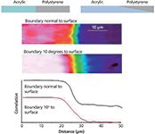
Figure 4: ATR images of two-layer samples.
Images of the two samples show that the edge appears much more diffuse in the sample where the boundary is at 10° to the surface (Figure 4). Penetration through the polystyrene layer a lows the acrylic material to be detected up to 10 µm away from the apparent boundary on the surface. Intensity profiles of the acrylic resin at different wavelengths clearly show how longer wavelengths detect the subsurface layer at greater depths. The profile at 1137 cm-1 is very unsymmetrical, extending about 15 µm beyond the surface boundary (Figure 5).
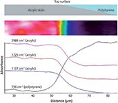
Figure 5: Specific frequency images.
Conclusions
In looking at reflection images it is important to remember that samples are three dimensional and that spectra may be generated from a finite volume, not just from the immediate surface. The boundaries between regions may, therefore, appear broader than those seen in visible images. This is most apparent in near-IR images where the resolution is likely to be limited by lateral scattering within the sample rather than by diffraction or the pixel size. In ATR images, the penet-ration depth allows spectral contributions to be seen from subsurface material.
Jerry Sellors and Richard Spragg are with PerkinElmer in Seer Green, Bucks, United Kingdom. Direct correspondence to: richard.spragg@perkinelmer.com
References
(1) F.C. Clarke et al., Appl. Spectrosc. 56(11), 1475 (2002).
(2) S.J. Hudak, K. Haber, G. Sando, L.H. Kidder, and E.N. Lewis, NIR News 18(6), 6 (2007).

New Study Provides Insights into Chiral Smectic Phases
March 31st 2025Researchers from the Institute of Nuclear Physics Polish Academy of Sciences have unveiled new insights into the molecular arrangement of the 7HH6 compound’s smectic phases using X-ray diffraction (XRD) and infrared (IR) spectroscopy.
Exoplanet Discovery Using Spectroscopy
March 26th 2025Recent advancements in exoplanet detection, including high-resolution spectroscopy, adaptive optics, and artificial intelligence (AI)-driven data analysis, are significantly improving our ability to identify and study distant planets. These developments mark a turning point in the search for habitable worlds beyond our solar system.
New Telescope Technique Expands Exoplanet Atmosphere Spectroscopic Studies
March 24th 2025Astronomers have made a significant leap in the study of exoplanet atmospheres with a new ground-based spectroscopic technique that rivals space-based observations in precision. Using the Exoplanet Transmission Spectroscopy Imager (ETSI) at McDonald Observatory in Texas, researchers have analyzed 21 exoplanet atmospheres, demonstrating that ground-based telescopes can now provide cost-effective reconnaissance for future high-precision studies with facilities like the James Webb Space Telescope (JWST) (1-3).